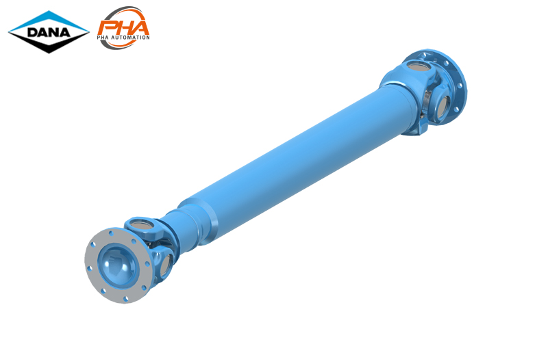
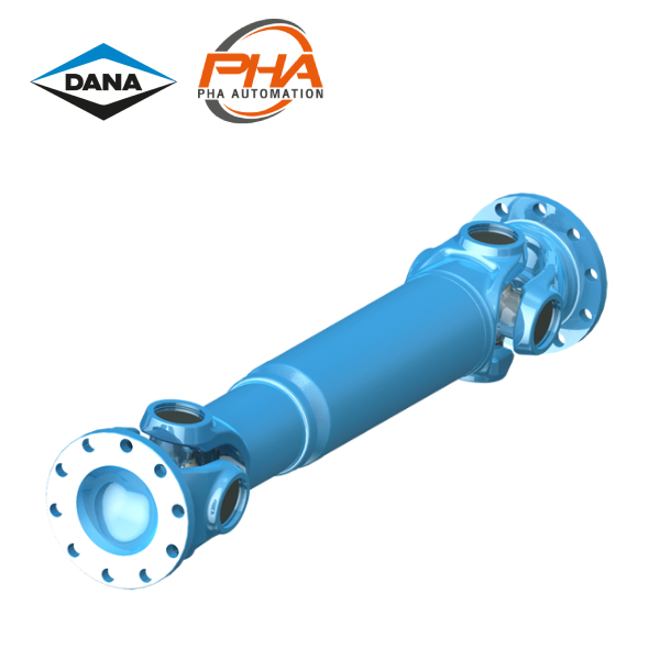
DANA Closed bearing eye - series 587

DANA Closed bearing eye – series 587
Feature | DANA Closed bearing eye 587
- Torque Range TCS : From 43 to 57 kNm
- Flange diameter : From 225mm to 28 5mm
- Field of application
- Railway vehicles
- Rolling mill plants
- Marine drives
- General machinery construction plants
Shaft specifications | DANA Closed bearing eye 587
- 0.01 with length compensation, tubular design
- 0.02 with large length compensation, tubular design
- 0.03 with length compensation, tubular design
- 9.01, 9.02, 9.03 with length compensation, short design
- 9.04 without length compensation, double flange shaft design
| Shaft size | 587.50 | 587.55 | 587.60 | ||||
|---|---|---|---|---|---|---|---|
| TCS | kNm | 43 | 52 | 57 | |||
| TDW | kNm | 13 | 23 | 23 | |||
| LC | – | 1.8 | 7.8 | 25.3 | |||
| β | <) °γ | 24 | 24 | 20 | 20 | 20 | 20 |
| A | mm | 225 | 250 | 250 | 285 | 285 | 285 |
| K | mm | 215 | 215 | 250 | 250 | 265 | 265 |
| B ±0.1mm | mm | 196 | 218 | 218 | 245 | 245 | 245 |
| Bs ±0.1mm | mm | – | 214 | 214 | – | 240 | – |
| C H7 | mm | 140 | 140 | 140 | 175 | 175 | 175 |
| F1) | mm | 4.4 | 5.4 | 5.5 | 6 | 6 | 6 |
| G | mm | 15 | 18 | 18 | 20 | 20 | 20 |
| H + 0.2mm | mm | 16.1 | 18.1 | 18.1 | 20.1 | 20.1 | 20.1 |
| Hs H12 | mm | – | 25 | 25 | – | 28 | – |
| I2) | – | 8 | 8 | 8 | 8 | 8 | 8 |
| Is3 | – | – | 4 | 4 | – | 4 | – |
| M | mm | 108 | 108 | 125 | 125 | 135 | 135 |
| S | mm | 144 x 7 | 144 x 7 | 167.7 x 9.8 | 167.7 x 9.8 | 167.7 x 9.8 | 167.7 x 9.8 |
| W DIN 5480 | mm | 90 x 2.5 | 90 x 2.5 | 120 x 2.5 | 120 x 2.5 | 120 x 2.5 | 120 x 2.5 |
- Tcs : Functional limit torque* : If the permissible function limit torque TCSis to ne fully uitilized, the flange connection (e.g., witth dowel pins) must be reinforced. Yieid torque 30% over TCS
- TDW : Reversing fatigue torque*
- LC : Bearing capacity factor* : See specifications of driveshafts.
- β : Maximum deflection angle per joint
- 1 Effective spigot depth
- 2 Number of flange holes (standard flange connection)
- 3 Number of flange holes (dowel pin connection)
Specification | DANA Closed bearing eye 587
| Design | Shaft size | 587.50 | 587.55 | 587.60 | ||||||||||||
|---|---|---|---|---|---|---|---|---|---|---|---|---|---|---|---|---|
| 0.01 | Lz min | – | – | 840 | 935 | 840 | 934 | 870 | 964 | |||||||
| La | – | – | 110 | 140 | 110 | 140 | 110 | 140 | ||||||||
| G | kg | – | 131 | 137 | 136 | 142 | 145 | 151 | ||||||||
| GR | kg | – | 38.2 | 38.2 | 38.2 | 38.2 | 38.2 | 38.2 | ||||||||
| Jm | kgm2 | – | 0.675 | 0.691 | 0.755 | 0.771 | 0.968 | 0.984 | ||||||||
| JmR | kgm2 | – | 0.239 | 0.239 | 0.239 | 0.239 | 0.239 | 0.239 | ||||||||
| C | Nm/rad. | – | 9.41 x 10⁵ | 9.37 x 10⁵ | 9.41 x 10⁵ | 9.37 x 10⁵ | 1.05 x 10⁶ | 1.04 x 10⁶ | ||||||||
| CR | Nm/rad. | – | 2.43 x 10⁶ | 2.43 x 10⁶ | 2.43 x 10⁶ | 2.43 x 10⁶ | 2.43 x 10⁶ | 2.43 x 10⁶ | ||||||||
| 0.02* | Lz min | mm | 800 | 800 | 1,185 | 1,185 | 1,215 | |||||||||
| La min | mm | 110 | 100 | 300 | 300 | 300 | ||||||||||
| G | kg | 86 | 91 | 165 | 170 | 189 | ||||||||||
| GR | kg | 23.7 | 23.7 | 38.2 | 38.2 | 38.2 | ||||||||||
| 0.03 | Lf | mm | 540 | 540 | 610 | 610 | 640 | |||||||||
| G | kg | 72 | 72 | 88 | 93 | 103 | ||||||||||
| GR | kg | 23.7 | 23.7 | 38.2 | 38.2 | 38.2 | ||||||||||
| Jm | kgm2 | 0.27 | 0.306 | 0.547 | 0.627 | 0.84 | ||||||||||
| JmR | kgm2 | 0.111 | 0.111 | 0.239 | 0.239 | 0.239 | ||||||||||
| C | Nm/rad. | 7.2 x 10⁵ | 7.2 x 10⁵ | 9.8 x 10⁵ | 9.8 x 10⁵ | 11.5 x 10⁵ | ||||||||||
| CR | Nm/rad. | 11.33 x 10⁵ | 11.33 x 10⁵ | 2.43 x 10⁶ | 2.43 x 10⁶ | 2.43 x 10⁶ | ||||||||||
| 9.01 | Lz min | mm | – | – | 823 | 823 | 843 | |||||||||
| La | mm | – | – | 100 | 100 | 100 | ||||||||||
| G | kg | – | – | 110 | 115 | 142 | ||||||||||
| Jm | kgm2 | – | – | 0.64 | 0.72 | 0.93 | ||||||||||
| C | Nm/rad. | – | – | 8.8 x 10⁵ | 8.8 x 10⁵ | 9.7 x 10⁵ | ||||||||||
| 9.02 | Lz | mm | – | – | 780 | 780 | 810 | |||||||||
| La | mm | – | – | 65 | 65 | 70 | ||||||||||
| G | kg | – | – | 108 | 113 | 125 | ||||||||||
| 9.03 | Lz | mm | 550 | 600 | 650 | 696 | 550 | 600 | 650 | 696 | 720 | 720 | 750 | |||
| La | mm | 60 | 75 | 90 | 110 | 60 | 75 | 90 | 110 | 65 | 65 | 65 | ||||
| G | kg | 61 | 66 | 68 | 70 | 66 | 71 | 73 | 75 | 113 | 118 | 126 | ||||
| 9.04 | Lf | mm | 432 | 432 | 500 | 500 | 540 | |||||||||
| G | kg | 58 | 68 | 81 | 91 | 110 | ||||||||||
- Lz min = Shortest possible compressed length
- La = Length compensation
- Lf min = Shortest fixed length
- Lz + La = Maximum operating length
- G = Weight of shaft
- GR = Weight per 1.000 mm tube
- Jm = Moment of inertia
- JmR = Moment of inertia per 1.000 mm tube
- C = Torsional stiffness of shaft without tube
- CR = Torsional stiffness per 1.000 mm tube
- * Larger length conpensation available on request
Lorem ipsum dolor sit amet, consectetuer adipiscing elit, sed diam nonummy nibh euismod tincidunt ut laoreet dolore magna aliquam erat volutpat.
ติดต่อแผนก HYDRAULIC


