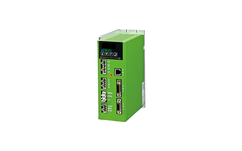
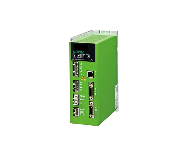
Hiwin Controller and Drive – Drive D1 : Achieved ultra-high positioning performance and excellent following feature to shorten positioning time effectively With the motion control technology of the semiconductor industry. Hiwin Controller and Drive – Drive D1 : In order to be compliant with the world trend, obtain the major international certifications: Provide motor short circuit detection, limit switch, emergency brake signal output, regenerative resistance and other protection measures. Provide a trial run interface with speed/acceleration protection settings, add-in settings, I/O tests, and complete analyses with filters and spectrums to propose a complete drive control solution.
Hiwin Controller and Drive – Drive D1
Controller & Drive – Drive D1
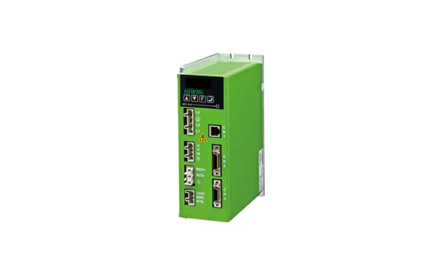
Feature | Controller and Drive – Drive D1
Code | Controller and Drive – Drive D1
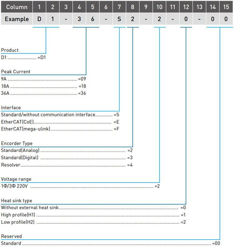
Model | Controller and Drive – Drive D1
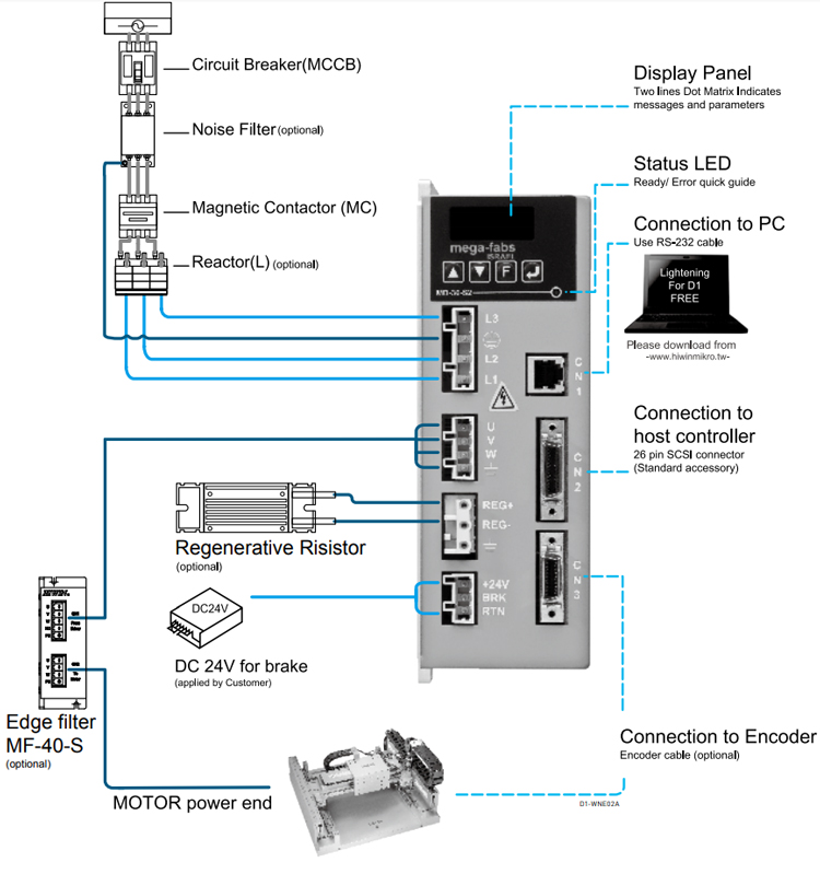
Specifications | Controller and Drive - Drive D1
D1 series
D1-09-XX ; D1-18-XX ; D1-36-XX
Voltage
1100-240 VAC ±10%
Frequency
50/60 Hz
Phase
1 Ø or 3 Ø
Control voltage
±24Vdc ±10%
Control current
1A minimum
Continuous current
D1-09:3Apk (2.12Arms)
D1-18:6Apk (4.24Arms)
D1-36:12Apk (8.5Arms)
(Note: External heat sink installed by depending on application)
Peak current
D1-09:9Apk (6.36Arms)
D1-18:18Apk (12.7Arms)
D1-36:36Apk (25.4Arms)
Continuous time of peak current
1 second
Main loop control
IGBT PWM spec vector control
Type of motor
AC servo motor, linear motor and torque motor
Status LED
Non EtherCAT drive
Red: Error; Green: Servo Ready
EtherCAT drive
Red: Error; Green: Run
*Control
Position mode
input port
(I9, I9M) (I10, I10M) Differential of I9, I10 single end input
Pules command mode
Pules/Direction
Maximum input frequency
differential
Pulse (2M Pulses/s max.);
Quad A/B(8M counts/s max.)
Single end
Pulse (500K Pulses/s max.);
Quad A/B (2N counts/s max.)
Command generator
Pulse from host controller
Command generator
Pulse from host controller
Position mode
Analog
Input resistance
10KΩ
Voltage
±10 Vdc
Electrical gear ratio
Dual wire type
I9 :PWM = 0% – 100%
I10 :Direction = 1/0
Single wire type
I9 :PWM = 50% ± 50%
I10 :Nonfunctional
Operation range
36.5 KHz minimum, 100KHz maximum
Pu;se width limit
220 ns minimum
Command generator
Voltage or PWM from host controller
Torque mode
Analog input Command
Same as velocity mode
Digital command format
Same as velocity mode
Command generator
Voltage or PWM from host controller
Encode Type
Operation voltage
+5Vdc±5% @400mA
Digital
Input signal
A, /A, B, /B, Z, /Z, RS422 differential signal
Bandwidth
5MHz line frequency, for AqB 20M Count/s
Analog
Input amplitude
1Vp-p (Sin/Cos), different signal
Bandwidth
1MHz maximum line (cycle) frequency
Resolution
Maximum 65528 Counts/cycle
Resolver
Resolution
12 bits(equival to a 1024 line quadrature encoder)
Rederence frequency
5KHz
Reference voltage
6Vp-p
Reference maximum current
100mA
*Output of Feedback pulse
Maximum 18M Count/s, RS422 differential output, Scaling adjustment
Hall signal
Single end signals with 120° phase difference: HA, HB, HC
Communication
Interface
RS232 to PC
Protocol
Full deplex, Baud rate: 115,200bps, Binary format
Programmable
10 digital inputs
Inputs (I1-I6, I11, I12)(I9, I10) -74HC14 Schmitt trigger input
3 digital outputs
0.3 Adc max, +40Vdc max (Open Drain)
(O1), (O2), (O3)
Brake output
BRAKE (O4), 1Adc max
PDL
Maximum code size
32K Bytes
Variable stroage capacity
800 Bytes
Support variable type
Floating : 32 bits
Integer : 16 and 32 bits; array and point
Execution cycle
66.67 us
Multitasking features
Execute 4Task at the same time
Instructions
if, else, while loop, for loop, goto and till
Operators
Contains the basic arithmetic operators, logical operators, comparison operators
Character length limitations
variable : 17, label : 24, proc : 24
Regen Circuit
Resistor
External
Turn on voltage
+HV > 390 Vdc
Turn off voltage
+HV < 380 Vdc
DC Bus capacitance
940uF/9A.18A
1880uF/36A
Protection
Short, Over voltage(> 400Vdc), Position error too big, Encoder error, Motor cable lost connection, Drive over-temperature (IGBT > 80°C±3°C), Motor over-tenperature, Under voltage(< 60Vdc)
Error Mapping
Applies to
Linear motor
Method
Established compensation table to compensate encoder error by linear interpolation
Samples
Maximum 5,000 points
Storage
Flash ROM, Disc file
Unit
um, count
Activation
Activated internally by home complete, or activated externally by input signal
functional frequency range of VSF
0.1~200 Hz
Environment
Operation Temperature
0-50°C (if over 55°C, air circulation is needed)
Storage Temperature
-20~65°C
Humidity
0 to 90%RH
Elevation
Under 1000 Meters
Vibration
1G (10 to 500Hz)
IP Code
IP20
Cooling System
Natural circulation and to install two types of heat sink
Weight
1,250 g(min)
Dimension
191.6 x 139.8 x 64.8 mm
Chassis
Compliance with U.L. Spec 94 V-0 Flammability Rating
ติดต่อ Hiwin, Linear Motion, Automation, Robot, System Intregration


