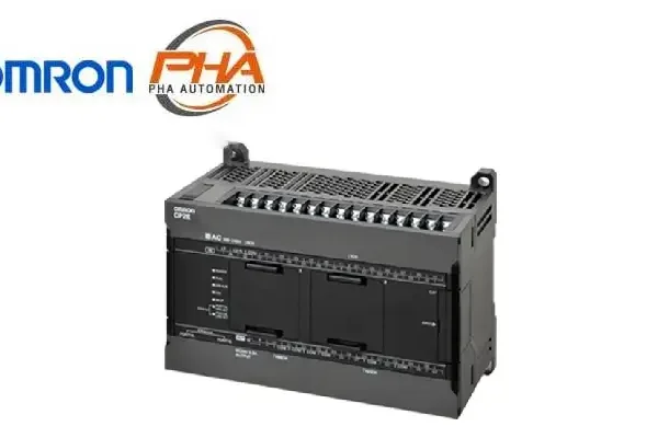
OMRON PLC - CP2E series
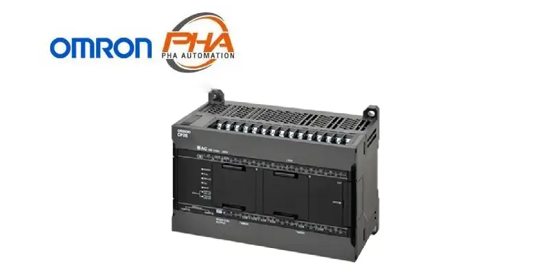
OMRON PLC – CP2E series
Model Numbers | PLC – CP2E series
Model Number Structure

Ordering Information
Applicable standards
Ask your OMRON representative for the most recent applicable standards for each model.
CPU Unit
CP2E-N-type/Network model
| Number of points |
Specifications | Model | |||||||
|---|---|---|---|---|---|---|---|---|---|
| Power Supply |
Inputs | Outputs | Output type |
Program capacity |
Data memory capacity |
Current consumption |
|||
| 5 VDC | 24 VDC | ||||||||
| CPU Units with 14 points  |
100 to 240 VAC |
8 points |
6 points |
Relay | 10K steps (FB capacity: 10K steps) |
16K words |
0.15 A | 0.05 A | CP2E-N14DR-A |
| Transistor (sinking) |
0.21 A | 0.02 A | CP2E-N14DT-A | ||||||
| 24 VDC | Relay | 0.15 A | 0.05 A | CP2E-N14DR-D | |||||
| Transistor (sinking) |
0.21 A | 0.02 A | CP2E-N14DT-D | ||||||
| Transistor (sourcing) |
0.22 A | 0.02 A | CP2E-N14DT1-D | ||||||
| CPU Units with 20 points  |
100 to 240 VAC |
12 points |
8 points |
Relay | 0.17 A | 0.06 A | CP2E-N20DR-A | ||
| Transistor (sinking) |
0.27 A | 0.02 A | CP2E-N20DT-A | ||||||
| 24 VDC | Relay | 0.17 A | 0.06 A | CP2E-N20DR-D | |||||
| Transistor (sinking) |
0.27 A | 0.02 A | CP2E-N20DT-D | ||||||
| Transistor (sourcing) |
0.26 A | 0.02 A | CP2E-N20DT1-D | ||||||
| CPU Units with 30 points  |
100 to 240 VAC |
18 points |
12 points |
Relay | 0.41 A | 0.07 A | CP2E-N30DR-A | ||
| Transistor (sinking) |
0.52 A | 0.03 A | CP2E-N30DT-A | ||||||
| 24 VDC | Relay | 0.37 A | 0.07 A | CP2E-N30DR-D | |||||
| Transistor (sinking) |
0.51 A | 0.03 A | CP2E-N30DT-D | ||||||
| Transistor (sourcing) |
0.51 A | 0.03 A | CP2E-N30DT1-D | ||||||
| CPU Units with 40 points  |
100 to 240 VAC |
24 points |
16 points |
Relay | 0.39 A | 0.09 A | CP2E-N40DR-A | ||
| Transistor (sinking) |
0.59 A | 0.03 A | CP2E-N40DT-A | ||||||
| 24 VDC | Relay | 0.39 A | 0.09 A | CP2E-N40DR-D | |||||
| Transistor (sinking) |
0.59 A | 0.03 A | CP2E-N40DT-D | ||||||
| Transistor (sourcing) |
0.59 A | 0.03 A | CP2E-N40DT1-D | ||||||
| CPU Units with 60 points  |
100 to 240 VAC |
36 points |
24 points |
Relay | 0.44 A | 0.13 A | CP2E-N60DR-A | ||
| Transistor (sinking) |
0.71 A | 0.03 A | CP2E-N60DT-A | ||||||
| 24 VDC | Relay | 0.41 A | 0.13 A | CP2E-N60DR-D | |||||
| Transistor (sinking) |
0.71 A | 0.03 A | CP2E-N60DT-D | ||||||
| Transistor (sourcing) |
0.71 A | 0.03 A | CP2E-N60DT1-D | ||||||
CP2E-S-type/Standard model
| Number of points |
Specifications | Model | |||||||
|---|---|---|---|---|---|---|---|---|---|
| Power Supply |
Inputs | Outputs | Output type |
Program capacity |
Data memory capacity |
Current consumption |
|||
| 5 VDC | 24 VDC | ||||||||
| CPU Units with 30 points  |
100 to 240 VAC |
18 points |
12 points |
Relay | 8K steps (FB capacity: 8K steps) |
8K words | 0.12 A | 0.07 A | CP2E-S30DR-A |
| 24 VDC | Transistor (sinking) |
0.28 A | 0.02 A | CP2E-S30DT-D | |||||
| Transistor (sourcing) |
CP2E-S30DT1-D | ||||||||
| CPU Units with 40 points  |
100 to 240 VAC |
24 points |
16 points |
Relay | 0.13 A | 0.09 A | CP2E-S40DR-A | ||
| 24 VDC | Transistor (sinking) |
0.34 A | 0.02 A | CP2E-S40DT-D | |||||
| Transistor (sourcing) |
CP2E-S40DT1-D | ||||||||
| CPU Units with 60 points  |
100 to 240 VAC |
36 points |
24 points |
Relay | 0.16 A | 0.13 A | CP2E-S60DR-A | ||
| 24 VDC | Transistor (sinking) |
0.48 A | 0.02 A | CP2E-S60DT-D | |||||
| Transistor (sourcing) |
CP2E-S60DT1-D | ||||||||
CP2E-E-type/Essential model
| Number of points |
Specifications | Model | |||||||
|---|---|---|---|---|---|---|---|---|---|
| Power Supply |
Inputs | Outputs | Output type |
Program capacity |
Data memory capacity |
Current consumption |
|||
| 5 VDC | 24 VDC | ||||||||
| CPU Units with 14 points 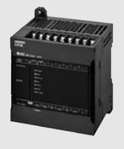 |
100 to 240 VAC |
8 points | 6 points | Relay | 4K steps (FB capacity: 4K steps) |
4K words | 0.06 A | 0.04 A | CP2E-E14DR-A |
| CPU Units with 20 points  |
12 points | 8 points | Relay | 0.08 A | 0.06 A | CP2E-E20DR-A | |||
| CPU Units with 30 points  |
18 points | 12 points | Relay | 0.12 A | 0.07 A | CP2E-E30DR-A | |||
| CPU Units with 40 points  |
24 points | 16 points | Relay | 0.13 A | 0.09 A | CP2E-E40DR-A | |||
| CPU Units with 60 points  |
36 points | 24 points | Relay | 0.16 A | 0.13 A | CP2E-E60DR-A | |||
Optional Products
Battery
| Product name | Specifications | Model |
|---|---|---|
Battery  |
Mounted in an N/S[][]-type CPU Unit. Mount the Battery when using the clock function. A Battery cannot be mounted to an E[][]-type CPU Unit. |
CP2W-BAT02 |
Option Board
| Product name | Specifications | Current consumption |
Model | |
|---|---|---|---|---|
| 5 VDC | 24 VDC | |||
| RS-232C Option Board  |
Mounted in the option slot of an N[][]-type CPU Unit and can be used as an RS-232C port. Maximum transmission distance: 15 m |
0.04 A | — | CP1W-CIF01 |
| Non-isolated RS-422A/485 Option Board  |
Mounted in the option slot of an N[][]-type CPU Unit and can be used as an RS-422A/485 port. Maximum transmission distance: 50 m |
0.04 A | — | CP1W-CIF11 |
| Isolated RS-422A/485 Option Board  |
Mounted in the option slot of an N[][]-type CPU Unit and can be used as an RS-422A/485 port. Maximum transmission distance: 500 m |
0.04 A | — | CP1W-CIF12-V1 |
| RS-232C&RS-232C Option Board  |
Mounted in the option slot of an N[][]-type CPU Unit and can be used as two RS-232C ports. Maximum transmission distance: 15 m |
0.04 A | — | CP2W-CIFD1 |
| RS-232C&RS-485 Option Board  |
Mounted in the option slot of an N[][]-type CPU Unit and can be used as one RS-232C port and one isolated RS-485 port. Maximum transmission distance: 15 m (RS-232C) 500 m (RS-485) |
0.06 A | — | CP2W-CIFD2 |
| RS-485&RS-485 Option Board  |
Mounted in the option slot of an N[][]-type CPU Unit and can be used as two isolated RS-485 ports. Maximum transmission distance: 500 m |
0.08 A | — | CP2W-CIFD3 |
| Analog Input Option Board  |
Mounted in the option slot of an N[][]-type CPU Unit and can be used as an analog input module. • 2 analog inputs 0 to 10 V (Resolution: 1/4000) 0 to 20 mA (Resolution: 1/2000) |
0.02 A | — | CP1W-ADB21 |
| Analog Output Option Board  |
Mounted in the option slot of an N[][]-type CPU Unit and can be used as an analog output module. • 2 analog outputs 0 to 10 V (Resolution: 1/4000) |
0.06 A | — | CP1W-DAB21V |
| Analog Input/Output Option Board  |
Mounted in the option slot of an N[][]-type CPU Unit and can be used as an analog input/output module. • 2 analog inputs 0 to 10 V (Resolution: 1/4000) 0 to 20 mA (Resolution: 1/2000) • 2 analog outputs 0 to 10 V (Resolution: 1/4000) |
0.08 A | — | CP1W-MAB221 |
Note: 1. Maximum one Analog Option Board can be mounted on an N[][]-type CPU Unit.
2. The CP1W-ME05M Memory Cassette, CP1W-DAM01 LCD Option Board, and CP1W-CIF41 Ethernet Option Board
cannot be used with the CP2E CPU Unit.
3. Option Boards cannot be used with the E/S[][]-type CPU Unit.
Expansion I/O Units and Expansion Units (for E30/40/60, S30/40/60, or N30/40/60 CPU Units)
E14/20 or N14/20 CPU Units do not support Expansion I/O Units and Expansion Units.
| Unit type | Product name |
Specifications | Current consumption (A) |
Model | ||||
|---|---|---|---|---|---|---|---|---|
| In- puts |
Out- puts |
Output type | 5 V | 24 V | ||||
| CP1W Expansion I/O Units |
Input Unit  |
8 | — | 24 VDC Input | 0.018 | — | CP1W-8ED | |
Output Units 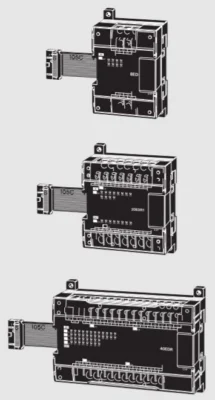 |
— | 8 | Relay | 0.026 | 0.044 | CP1W-8ER | ||
| Transistor (sinking) | 0.075 | — | CP1W-8ET | |||||
| Transistor (sourcing) | 0.075 | — | CP1W-8ET1 | |||||
| — | 16 | Relay | 0.042 | 0.090 | CP1W-16ER | |||
| Transistor (sinking) | 0.076 | — | CP1W-16ET | |||||
| Transistor (sourcing) | 0.076 | — | CP1W-16ET1 | |||||
| — | 32 | Relay | 0.049 | 0.131 | CP1W-32ER | |||
| Transistor (sinking) | 0.113 | — | CP1W-32ET | |||||
| Transistor (sourcing) | 0.113 | — | CP1W-32ET1 | |||||
I/O Units  |
12 | 8 | Relay | 0.103 | 0.044 | CP1W-20EDR1 | ||
| Transistor (sinking) | 0.130 | — | CP1W-20EDT | |||||
| Transistor (sourcing) | 0.130 | — | CP1W-20EDT1 | |||||
| 24 | 16 | Relay | 0.080 | 0.090 | CP1W-40EDR | |||
| Transistor (sinking) | 0.160 | — | CP1W-40EDT | |||||
| Transistor (sourcing) | 0.160 | — | CP1W-40EDT1 | |||||
| CP1W Expansion Units |
Analog Input Unit  |
4CH | — | Input range: 0 to 5 V, 1 to 5 V, 0 to 10 V, ±10 V, 0 to 20 mA, or 4 to 20 mA. |
Resolution: 1/6000 |
0.100 | 0.090 | CP1W-AD041 |
| Resolution: 1/12000 |
0.100 | 0.050 | CP1W-AD042 | |||||
| Analog Output Unit  |
— | 2CH | Output range: 1 to 5 V, 0 to 10 V, ±10 V, 0 to 20 mA, or 4 to 20 mA. |
Resolution: 1/6000 |
0.040 | 0.095 | CP1W-DA021 | |
| — | 4CH | Resolution: 1/6000 |
0.080 | 0.124 | CP1W-DA041 | |||
| Resolution: 1/12000 |
0.070 | 0.160 | CP1W-DA042 | |||||
Analog I/O Unit  |
4CH | 4CH | Input range: 0 to 5 V, 1 to 5 V, 0 to 10 V, ±10 V, 0 to 20 mA, or 4 to 20 mA. Output range: 1 to 5 V, 0 to 10 V, ±10 V, 0 to 20 mA, or 4 to 20 mA. |
Resolution: 1/12000 |
0.120 | 0.170 | CP1W-MAD44 | |
| 4CH | 2CH | Resolution: 1/12000 |
0.120 | 0.120 | CP1W-MAD42 | |||
| 2CH | 1CH | Resolution: 1/6000 |
0.083 | 0.110 | CP1W-MAD11 | |||
| Temperature Sensor Unit  |
2CH | — | Sensor type: Thermocouple (J or K) | 0.040 | 0.059 | CP1W-TS001 | ||
| 4CH | — | Sensor type: Thermocouple (J or K) | 0.040 | 0.059 | CP1W-TS002 | |||
| 2CH | — | Sensor type: Platinum resistance thermometer (Pt100 or JPt100) |
0.054 | 0.073 | CP1W-TS101 | |||
| 4CH | — | Sensor type: Platinum resistance thermometer (Pt100 or JPt100) |
0.054 | 0.073 | CP1W-TS102 | |||
| 4CH | — | Sensor type: Thermocouple (J or K) 2channels can be used as analog input. Input range: 1 to 5 V, 0 to 10 V, 4-20 mA |
Resolution: 1/12000 |
0.070 | 0.030 | CP1W-TS003 | ||
| 12CH | — | Sensor type: Thermocouple (J or K) | 0.080 | 0.050 | CP1W-TS004 | |||
I/O Connecting Cable
| Product name | Specifications | Model |
|---|---|---|
| I/O Connecting Cable | 80 cm (for CP1W Expansion I/O Units and Expansion Units) Only one I/O Connecting Cable can be used in each PLC. |
CP1W-CN811 |
Recommended Ethernet Communications Cables
For the Ethernet communications cable specifications, refer to Catalog
| Item | Recommended manufacturer |
Cable length (m) |
Model | |
|---|---|---|---|---|
| Wire Gauge and Number of Pairs: AWG26, 4-pair Cable Cable Sheath material: LSZH *2 |
Cable with Connectors on Both Ends (RJ45/RJ45) Standard RJ45 plug type *1 Cable color: Yellow *3  |
OMRON | 0.3 | XS6W-6LSZH8SS30CM-Y |
| 0.5 | XS6W-6LSZH8SS50CM-Y | |||
| 1 | XS6W-6LSZH8SS100CM-Y | |||
| 2 | XS6W-6LSZH8SS200CM-Y | |||
| 3 | XS6W-6LSZH8SS300CM-Y | |||
| 5 | XS6W-6LSZH8SS500CM-Y | |||
| Wire Gauge and Number of Pairs: AWG22, 2-pair cable |
Cable with Connectors on Both Ends (RJ45/RJ45) Rugged RJ45 plug type *1 Cable color: Light blue  |
OMRON | 0.3 | XS5W-T421-AMD-K |
| 0.5 | XS5W-T421-BMD-K | |||
| 1 | XS5W-T421-CMD-K | |||
| 2 | XS5W-T421-DMD-K | |||
| 5 | XS5W-T421-GMD-K | |||
| 10 | XS5W-T421-JMD-K | |||
*1. Cables with standard RJ45 plugs are available in the following lengths: 0.2 m, 0.3 m, 0.5 m, 1 m, 1.5 m, 2 m, 3 m, 5 m, 7.5 m, 10 m, 15 m, 20 m.
Cables with rugged RJ45 plugs are available in the following lengths: 0.3 m, 0.5 m, 1 m, 2 m, 3 m, 5 m, 10 m, 15 m.
For details, refer to the Industrial Ethernet Connectors Catalog (Cat. No. G019).
*2. The lineup features Low Smoke Zero Halogen cables for in-cabinet use and PUR cables for out-of-cabinet use.
Although the LSZH cable is single shielded, its communications and noise characteristics meet the standards.
*3. Cable colors are available in yellow, green, and blue.
*4. For details, contact your OMRON representative.
RS-232C Connecting Cable
| Name | Specifications | Model | |
|---|---|---|---|
| PT-to-PLC Connecting Cable |
Connection cable with programmable terminal NB / NS For CP2E-N+CP1W-CIF01 |
Length: 2 m | XW2Z-200T |
| Length: 5 m | XW2Z-500T | ||
| Connection cable with programmable terminal NB / NS For CP2E-S/E, CP2E-N+CP2W-CIFD1/CIFD2 |
Length: 2 m | XW2Z-200T-3 | |
| Length: 5 m | XW2Z-500T-3 | ||
DIN Track Accessories
| Name | Specifications | Model | |
|---|---|---|---|
| DIN Track | Length: 0.5 m; Height: 7.3 mm | PFP-50N | |
| Length: 1 m; Height: 7.3 mm | PFP-100N | ||
| Length: 1 m; Height: 16 mm | PFP-100N2 | ||
| End Plate | A stopper to secure the Units on the DIN Track. | PFP-M | |
Programming Devices
Software
| Product name |
Specifications | Model | ||
|---|---|---|---|---|
| Number of licenses |
Media | |||
| FA Integrated Tool Package CX-One Lite Ver.4.[] |
CX-One Lite is a subset of the complete CX-One package that provides only the Support Software required for micro PLC applications. CX-One Lite runs on the following OS. OS: Windows 7 (32-bit/64-bit version) / Windows 8 (32-bit/64-bit version) / Windows 8.1 (32-bit/64-bit version) / Windows 10 (32-bit/64-bit version) CX-One Lite Ver. 4.[] includes Micro PLC Edition CX-Programmer Ver.9.[]. |
1 license | DVD | CXONE-LT01D-V4 |
| FA Integrated Tool Package CX-One Package Ver. 4.[] |
CX-One is a comprehensive software package that integrates Support Software for OMRON PLCs and components. CX-One runs on the following OS. OS: Windows 7 (32-bit/64-bit version) / Windows 8 (32-bit/64-bit version) / Windows 8.1 (32-bit/64-bit version) / Windows 10 (32-bit/64-bit version) CX-One Ver. 4.[] includes CX-Programmer Ver. 9.[]. |
1 license *1 |
DVD | CXONE-AL01D-V4 |
Note: 1. CP2E CPU Units are supported by CX-One version 4.51 or higher and CX-Programmer version 9.72 or higher.
2. The CX-One and CX-One Lite cannot be simultaneously installed on the same computer.
3. For details, refer to the CX-One Catalog (Cat. No. R134).
*1. Multi licenses (3, 10, 30, or 50 licenses) and DVD media without licenses are also available for the CX-One.
Specifications | PLC – CP2E series
General Specifications
| Item | AC power supply | DC power supply | |
|---|---|---|---|
| Model | CP2E-[][][]D[]-A | CP2E-[][][]D[]-D | |
| Enclosure | Mounted in a panel | ||
| Dimensions (H × D × W) | CPU Unit with 14 or 20 I/O points (CP2E-[]14/20D[]-[]): 90mm *1 ×80mm *2 × 86mm CPU Unit with 30 I/O points (CP2E-[]30D[]-[]): 90mm *1 × 80mm *2 × 130mm CPU Unit with 40 I/O points (CP2E-[]40D[]-[]): 90mm *1 × 80mm *2 × 150mm CPU Unit with 60 I/O points (CP2E-[]60D[]-[]): 90mm *1 × 80mm *2 × 195mm |
||
| Weight | CPU Unit with 14 I/O points (CP2E-[]14D[]-[]): 335g max. CPU Unit with 20 I/O points (CP2E-[]20D[]-[]): 340g max. CPU Unit with 30 I/O points (CP2E-[]30D[]-[]): 580g max. CPU Unit with 40 I/O points (CP2E-[]40D[]-[]): 640g max. CPU Unit with 60 I/O points (CP2E-[]60D[]-[]): 780g max. |
||
| Electrical specifications |
Supply voltage | 100 to 240 VAC 50/60 Hz | 24 VDC |
| Operating voltage range |
85 to 264 VAC | 20.4 to 26.4 VDC | |
| Power consumption |
15 VA/100 VAC max. 25 VA/240 VAC max. (CP2E-[]14/20D[]-A) |
13W max. (CP2E-[]14/20D[]-D) | |
| 50 VA/100 VAC max. 70 VA/240 VAC max. (CP2E-[]30/40/60D[]-A) |
20W max. (CP2E-[]30/40/60D[]-D) *4 | ||
| Inrush current | 120 VAC, 20 A for 8 ms max. for cold start at room temperature 240 VAC, 40 A for 8 ms max. for cold start at room temperature |
24 VDC, 30A for 20 ms max. for cold start at room temperature |
|
| External power supply *3 |
Not provided. (CP2E-[]14/20D[]-A) 24 VDC, 300 mA (CP2E-[]30/40/ 60D[]-A) |
Not provided. | |
| Insulation resistance |
20 MΩ min. (at 500 VDC) between the external AC terminals and GR terminals |
Not csolated between primary and secondary DC power supplies |
|
| Dielectric strength | 2,300 VAC 50/60Hz for 1 min between AC external and GR terminals Leakage current: 5 mA max. |
Not csolated between primary and secondary DC power supplies |
|
| Power interrupt time |
10 ms min. | 2 ms min. | |
| Application environment |
Ambient operating temperature |
-20 to 60°C | |
| Ambient humidity | 10% to 90% | ||
| Atmosphere | No corrosive gas. | ||
| Ambient storage temperature |
-20 to 75°C (excluding battery) | ||
| Altitude | 2,000 m max. | ||
| Pollution degree | 2 or less: Conforms to IEC61010-2-201. | ||
| Noise resistance | 2 kV on power supply line (Conforms to IEC61000-4-4.) | ||
| Overvoltage category |
Category II: Conforms to IEC61010-2-201. | ||
| EMC immunity level |
Zone B | ||
| Vibration resistance |
Conforms to IEC60068-2-6. 5 to 8.4 Hz with 3.5-mm amplitude, 8.4 to 150 Hz Acceleration of 9.8 m/s2 for 100 min in X, Y, and Z directions (10 sweeps of 10 min each = 100 min total) |
||
| Shock resistance | Conforms to IEC60068-2-27. 147 m/s2, 3 times in X, Y, and Z directions |
||
| Terminal block | Fixed (not removable) | ||
| Terminal screw size | M3 | ||
| Applicable standards | Conforms to EC Directives, KC, UL and EAC. | ||
| Grounding method | Ground to 100Ω or less. | ||
*1. Total of 110 mm with mounting brackets.
*2. Excluding cables.
*3. Use the external power supply to power input devices. Do not use it to drive output devices.
*4. This is the rated value for the maximum system configuration. Use the following formula to calculate power
consumption for CPU Units with DC power.
Formula: DC power consumption = (5V current consumption × 5 V/70% (internal power efficiency) + 24V current
consumption) × 1.1 (current fluctuation factor)
The above calculation results show that a DC power supply with a greater capacity is required.
Note: 1. The Expansion I/O Units and Expansion Units work under the same conditions as the CPU Units unless otherwise
specified.
Performance Specifications
| Item | CP2E-E[][]D[]-[] | CP2E-S[][]D[]-[] | CP2E-N[][]D[]-[] | ||
|---|---|---|---|---|---|
| Program capacity | 4K steps | 8K steps | 10K steps | ||
| FB capacity | 4K steps | 8K steps | 10K steps | ||
| Control method | Stored program method | ||||
| I/O control method | Cyclic scan with immediate refreshing | ||||
| Program language | Ladder diagram | ||||
| Function blocks | Maximum number of function block definitions: 64 Maximum number of instances: 128 Languages usable in function block definitions: Ladder diagrams, structured text (ST) |
||||
| Instructions | Approximately 220 | ||||
| Proc- essing speed |
Overhead processing time | 0.1 ms | 0.15 ms | 0.2 ms | |
| Instruction execution times | LD 0.23 μs MOV 1.76 μs |
||||
| Number of CP1W-series Expansion I/O Units and Expansion Units connected |
CP2E-[]14/20D[]-[]: None CP2E-[]30/40/60D[]-[]: 3 units |
||||
| Maximum number of I/O points | CP2E-[]14D[]-[]: 14 CP2E-[]20D[]-[]: 20 CP2E-[]30D[]-[]: 150 (30 built in, 40 × 3 expansion) CP2E-[]40D[]-[]: 160 (40 built in, 40 × 3 expansion) CP2E-[]60D[]-[]: 180 (60 built in, 40 × 3 expansion) |
||||
| Built-in input function |
High- speed counters |
High-speed counter mode/ maximum frequency |
Incremental Pulse Inputs 100 kHz: 2 counters 10 kHz: 4 counters Up/Down Inputs 100 kHz: 1 counter 10 kHz: 1 counter Pulse + Direction Inputs 100 kHz: 2 counters Differential Phase Inputs (4x) 50 kHz: 1 counter 5 kHz: 1 counter |
N14/20D[]-[] Incremental Pulse Inputs 100 kHz: 2 counters 10 kHz: 4 counters Up/Down Inputs 100 kHz: 1 counter 10 kHz: 1 counter Pulse + Direction Inputs 100 kHz: 2 counters Differential Phase Inputs (4x) 50 kHz: 1 counter 5 kHz: 1 counter N30/40/60D[]-[] |
|
| Counting mode | • Linear mode • Ring mode |
||||
| Count value | 32 bits | ||||
| Counter reset modes |
• Phase Z and software reset (excluding increment pulse input) • Software reset |
||||
| Control method | • Target matching • Range comparison |
||||
| Input interrupts | 6 inputs | 8 inputs (6 inputs only for 14 I/O points) |
|||
| Interrupt input pulse width: 50 µs min. | |||||
| Quick-response inputs | 6 inputs | 8 inputs (6 inputs only for 14 I/O points) |
|||
| Input pulse width: 50 µs min. | |||||
| Normal input |
Input constants | Delays can be set in the PLC setup (0 to 32 ms, default: 8 ms). Set values: 0, 1, 2, 4, 8, 16, or 32 ms |
|||
| Built-in output function |
Pulse outputs (Models with transistor outputs only) |
Pulse output | Pulse output function not included |
Pulse + Direction Mode | |
| Frequency | 1 Hz to 100kHz: 2 outputs |
N14/20D[]-[] 1 Hz to 100kHz: 2 outputs N30/40/60D[]-[] 1 Hz to 100kHz: 4 outputs |
|||
| Output mode | • Continuous mode (for speed control) • Independent mode (for position control) |
||||
| Number of output pulses |
• Relative coordinates: 0000 0000 to 7FFF FFFF hex (0 to 2147483647) • Absolute coordinates: 8000 0000 to 7FFF FFFF hex (-2147483647 to 2147483647) |
||||
| Acceleration/ deceleration curves |
Trapezoidal acceleration and deceleration (Cannot perform S-curve acceleration and deceleration). |
||||
| Changing SVs during instruction execution |
Only target position can be changed. | ||||
| Origin searches | Included | ||||
| Linear interpolation |
None | N14/20D[]-[] 2 axes max. N30/40/60D[]-[] 4 axes max. |
|||
| PWM output (transistor outputs models only) |
Frequency | PWM output function not included | 2.0 to 6,553.5 Hz (in increments of 0.1 Hz) with 1 output or 2 Hz to 32,000 Hz (in increments of 1 Hz) with 1 output |
||
| Duty factor | 0.0% to 100.0% (in increments of 0.1%) Accuracy: +1%/-0% at 2 Hz to 10,000 Hz and +5%/-0% at 10,000 Hz to 32,000 kHz |
||||
| Output mode | Continuous Mode | ||||
| Communications | Peripheral USB port | Conforming to USB 2.0 B-type conntor | None | ||
| Transmission distance |
5 m max. | ||||
| Built-in RS232C port | Interface: Conforming to EIA RS-232C | None | |||
| Transmission distance |
15 m max. | ||||
| Communications method |
Half duplex | ||||
| Synchronization | Start-stop | ||||
| Baud rate | 1.2, 2.4, 4.8, 9.6, 19.2, 38.4, 57.6, or 115.2 kbps |
||||
| Supported protocol |
• Host Link • 1:N NT Link • No-protocol mode • Serial PLC Links (master, slave) • Modbus-RTU Easy Master • Modbus-RTU Slave |
||||
| Built-in RS485 port (not isolated) |
None | Interface: Conforming to EIA RS-485 |
None | ||
| Transmission distance |
50 m max. | ||||
| Communications method |
Half duplex | ||||
| Synchronization | Start-stop | ||||
| Baud rate | 1.2, 2.4, 4.8, 9.6, 19.2, 38.4, 57.6, or 115.2 kbps |
||||
| Supported protocol |
• Host Link • 1:N NT Link • No-protocol mode • Serial PLC Links (master, slave) • Modbus-RTU Easy Master • Modbus-RTU Slave |
||||
| Serial Option port | Number of Option Boards |
None | N14/20D[]-[] 1 Option Board N30/40/60D[]-[] 2 Option Boards |
||
| Number of serial communications |
N14/20D[]-[] 2 ports max. N30/40/60D[]-[] 3 ports max. |
||||
| Communications method |
Depends on Option Board | ||||
| Synchronization | Depends on Option Board | ||||
| Baud rate | 1.2, 2.4, 4.8, 9.6, 19.2, 38.4, 57.6, or 115.2 kbps |
||||
| Mountable Option Boards | Serial Communication Option Board with one port • One RS-232C port: CP1W-CIF01 (Start-stop) • One RS-422A/485 port (not isolated): CP1W-CIF11 (Start-stop) • One RS-422A/485 port (isolated): CP1W-CIF12-V1 (Start-stop) Serial Communication Option Board with two ports *1 • Two RS-232C ports: CP2W-CIFD1 (Start-stop) • One RS-232C port and one RS- 485 port (isolated): CP2W-CIFD2 (Start-stop) • Two RS-485 ports (isolated): CP2W-CIFD3 (Start-stop) Analog Option Board *2 CP1W-MAB221/ADB21/DAB21V *1. CP2W-CIFD[] can only be mounted on option slot 1. *2. Maximum one Analog Option Board can be mounted on an N[][]-type CPU Unit. |
||||
| Compatible protocols | • Host Link* • 1:N NT Link* • No-protocol mode • Serial PLC Links (master, slave) • Modbus-RTU Easy Master • Modbus-RTU Slave * PORT1 (EX) is not supported. |
||||
| Ethernet | Physical layer | None | 100/10BASE-TX (Auto-MDIX) | ||
| Media access methiod | CSMA/CD | ||||
| Modulation | Baseband | ||||
| Baud rate | 100BASE-TX: 100Mbit/s 10BASE-T: 10Mbit/s • Half/full auto-negotiation for each port • Link speed auto-sensing for each port |
||||
| Transmission media |
100BASE-TX • Unshielded twisted-pair (UDP) cable Categories: 5, 5e • Shielded twisted-pair (STP) cable Categories: 100Ω at 5, 5e 10BASE-T • Unshielded twisted-pair (UDP) cable Categories: 3, 4, 5, 5e • Shielded twisted-pair (STP) cable Categories: 100Ω at 3, 4, 5, 5e |
||||
| Transmission distance | 100 m (distance between switch and node) |
||||
| Protocol | TCP, UDP, APR, ICMP (ping only), SNTP, DNS |
||||
| Applications | FINS, Socket, SNTP, DNS (Client) |
||||
| Number of Ethernet ports | N14/20: 1 port N30/40/60: 2 ports |
||||
| Ethernet switch | Layer 2 switch * N14/20 is not supported. |
||||
| Number of tasks | 17 • 1 cyclic task • 16 interrupt tasks Scheduled interrupt task: Interrupt task 1 (fixed) Built-in input interrupt task: Interrupt task 2 to 9 (IN8 and IN9 can only be used in N20/30/40/60 CPU Units) High-speed counter interrupt task: Interrupt task 1 to 16 |
||||
| Maximum subroutine number | 128 | ||||
| Maximum jump number | 128 | ||||
| Scheduled interrupt tasks | 1 interrupt task | ||||
| Battery service life *With CP2W-BAT02 Battery (optional) |
Battery cannot be mounted. |
CP2W-BAT02 can be mounted. Maximum battery service life: 5 years Guaranteed Lifetime Ambient temperature is 60°C: 13,000 hours (approx. 1.5 years) Ambient temperature is 25°C: 43,000 hours (approx. 5 years) |
|||
| Clock | None | Supported. Accuracy (monthly deviation): -4.5 min to -0.5 min (ambient temperature: 60°C), -2.0 min to +2.0 min (ambient temperature: 25°C), -2.5 min to +1.5 min (ambient temperature: -20°C) |
|||
| Memory backup |
Built-in Flash Memory | Ladder programs and parameters are automatically saved to built-in Flash Memory. A section of the Data Memory Area can be saved to the built-in Flash Memory. |
|||
| Built-in non-volatile memory | Data Memory Area (D), Holding Area (H), Counter Area (C) and Auxiliary Area (A) are automatically saved to the built-in non-volatile memory. |
||||
| CIO Area |
Input Bits | 1,600 bits (100 words): CIO 0.00 to CIO 99.15 (CIO 00 to CIO 99) | |||
| Output Bits | 1,600 bits (100 words): CIO 100.00 to CIO 199.15 (CIO 100 to CIO 199) | ||||
| Serial PLC Link Words | 1,440 bits (90 words): CIO 200.00 to CIO 289.15 (CIO 200 to CIO 289) | ||||
| Work Area (W) | 2,048 bits (128 words): W0.00 to W127.15 (W0 to W127) | ||||
| Holding Area (H) | 2,048 bits (128 words): H0.00 to H127.15 (H0 to 127) Words H512 to H1535: These words can be used only for function blocks. |
||||
| Auxiliary Area (A) | Read-only: 7,168 bits (448 words): A0.00 to A447.15 (A0 to A447) Read/write: 8,192 bits (512 words): A448.00 to A959.15 (A448 to A959) |
||||
| Temporary Area (TR) | 16 bits: TR0 to TR15 | ||||
| Timer Area (T) | 256 timer numbers (T0 to T255 (separate from counters)) Words T256 to T511: These words can be used only for function blocks. |
||||
| Counter Area (C) | 256 counter numbers (C0 to C255 (separate from timers)) Words C256 to C511: These words can be used only for function blocks. |
||||
| Data Memory Area (D) | 4 K words: D0 to D4095 DM backup: 1,500 words (D0 to D1499) |
8 K words: D0 to D8191 DM backup: 7,000 words (D0 to D6999) |
16 K words: D0 to D16383 DM backup: 15,000 words (D0 to D14999) |
||
| Index Registers (IR) | 16 registers: IR0 to IR15 | ||||
| Data Registers (DR) | 16 registers: DR0 to DR15 | ||||
| Operating modes | PROGRAM Mode: Program execution is stopped. Preparations can be executed prior to program execution in this mode. MONITOR Mode: Programs are executed. Some operations, such as online editing, and changes to present values in I/O memory, are enabled in this mode. RUN Mode: Programs are executed. This is the normal operating mode. |
||||
Dimensions | PLC – CP2E series
(Unit: mm)
CPU Units with 14 or 20 I/O Points
CP2E-N14/20D[]-[]
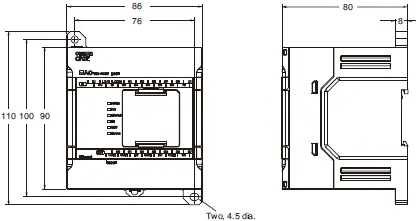
CP2E-E14/20D[]-[]
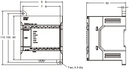
CPU Units with 30 I/O Points
CP2E-N30D[]-[]
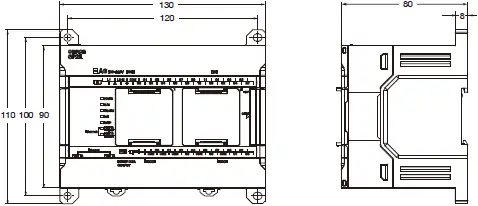
CP2E-E30D[]-[], CP2E-S30D[]-[]
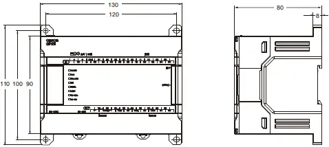
CPU Units with 40 I/O Points
CP2E-N40D[]-[]
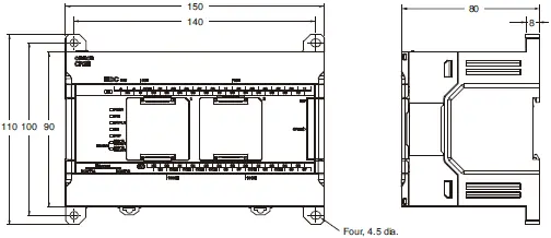
CP2E-E40D[]-[], CP2E-S40D[]-[]
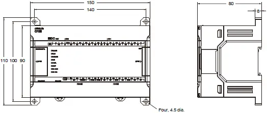
CPU Units with 60 I/O Points
CP2E-N60D[]-[]
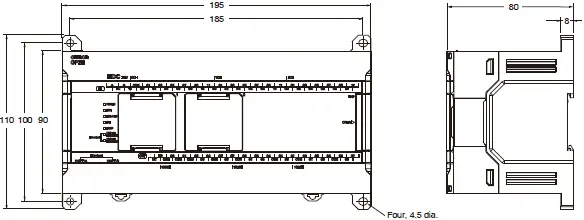
CP2E-E60D[]-[], CP2E-S60D[]-[]
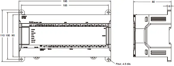
Expansion I/O Units and Expansion Units
CP1W-8E[][]
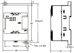
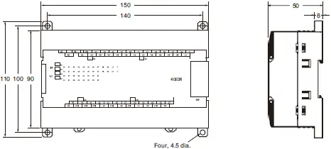
CP1W-20ED[]/CP1W-16E[][]/CP1W-AD04[]/CP1W-DA021/CP1W-DA04[]/CP1W-MAD[][]/CP1W-TS[][]1/[][]2/[][]3

CP1W-40ED[]/CP1W-32E[][]/CP1W-TS004
Features | PLC – CP2E series
The CP2E Series is an automatic control device (PLC) that offers a wide range of functions for the machine. Improved EtherNet connectivity and LED devices display and settings.
Properties | PLC – CP2E series
| PLC | CP2E series |
|---|---|
| Power Supply | 24 VDC (CP2E-[][][]D[]-D) 100 to 240 VAC 50/60 Hz (CP2E-[][][]D[]-A) |
| Power consumption | CP2E-[][][]D[]-A -15 VA/100 VAC Max, 25 VA/240 VAC Max (CP2E-[]14/20D[]-A) – 50 VA/100 VAC Max, 70 VA/240 VAC Max (CP2E-[]30/40/60D[]-A) CP2E-[][][]D[]-D – 13 W Max (CP2E-[]14/20D[]-D) – 20 W Max (CP2E-[]30/40/60D[]-D) |
| Max Point I/O | – 14 (CP2E-[]14D[]-[]) – 20 (CP2E-[]20D[]-[]) – 150 (built in 30, expansion 40×3) (CP2E-[]30D[]-[]) – 160 (built in 40, expansion 40×3) (CP2E-[]40D[]-[]) – 180 (built in 60, expansion 40×3) (CP2E-[]60D[]-[]) |
| Communication | – Peripheral USB port – EtherNet Port |
| Program capacity | – 4K steps (CP2E-E[][]D[]-[]) – 8K steps (CP2E-S[][]D[]-[]) – 10K steps (CP2E-N[][]D[]-[]) |
| Size (W x H x D) (mm) | – 86 x 90 x 80 (CP2E-[]14/20D[]-[]) – 130 x 90 x 80 (CP2E-[]30D[]-[]) – 150 x 90 x 80 (CP2E-[]40D[]-[]) – 195 x 90 x 80 (CP2E-[]60D[]-[]) |
| Weight (g) | – 335 (CP2E-[]14D[]-[]) – 340 (CP2E-[]20D[]-[]) – 580 (CP2E-[]30D[]-[]) – 640 (CP2E-[]40D[]-[]) – 780 (CP2E-[]60D[]-[]) |
ติดต่อแผนก Automation & Robots


