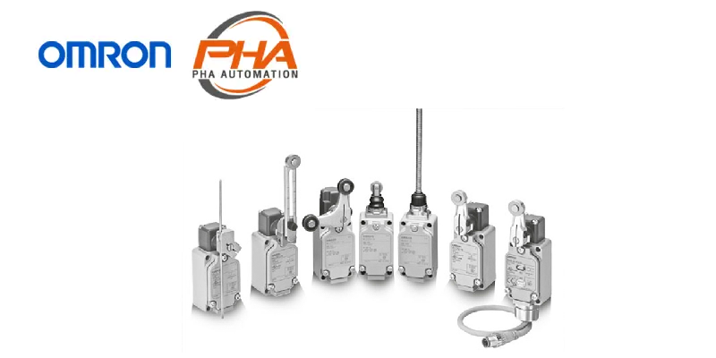
OMRON Limit Switches – WL-N / WL
Model Numbers | Limit Switches – WL-N / WL
General-purpose Switches
Model Number Structure
Model Number Legend (Not all combinations are possible. Ask your OMRON representative for details.)
Basic models

High-sensitivity and High-precision Models

Ordering Information
Roller Lever
Standard built-in switch
| Appear- ance |
Actuator | Terminal shape |
Pretravel (PT) |
Without operation indicator |
With operation indicator * | |
|---|---|---|---|---|---|---|
| LED | Neon lamp | |||||
| Model | Model | Model | ||||
 |
Roller lever: R38 mm |
Screw terminals (Conduit size: G½) |
15±5° | WLCA2-N | WLCA2-LD-N | WLCA2-LE-N |
| 25±5° | WLCA2-2-N | WLCA2-2LD-N | WLCA2-2LE-N | |||
| 20° max. | WLCA2-2N-N | WLCA2-2NLD-N | WLCA2-2NLE-N | |||
| 10°+2°,-1° | WLG2 | WLG2-LD | WLG2-LE | |||
| 5°+2°, 0° | WLGCA2 | WLGCA2-LD | WLGCA2-LE | |||
 |
Roller lever: R50 mm |
15±5° | WLCA2-7-N | WLCA2-7LD-N | WLCA2-7LE-N | |
| 25±5° | — | — | — | |||
| 20° max. | — | — | — | |||
 |
Roller lever: R63 mm |
15±5° | WLCA2-8-N | WLCA2-8LD-N | WLCA2-8LE-N | |
| 25±5° | — | — | — | |||
| 20° max. | — | — | — | |||
 |
Adjustable roller lever (R25 to 89 mm) |
15±5° | WLCA12-N | WLCA12-LD-N | WLCA12-LE-N | |
| 25±5° | WLCA12-2-N | WLCA12-2LD-N | WLCA12-2LE-N | |||
| 20° max. | WLCA12-2N-N | WLCA12-2NLD-N | WLCA12-2NLE-N | |||
| 10°+2°,-1° | WLG12 | WLG12-LD | WLG12-LE | |||
* The default setting is light-ON when not operating (NO wiring). Turn the lamp holder by 180° to change the setting to light-
ON when operating (NC wiring).
| Appear- ance |
Actuator | Terminal shape |
Pretravel (PT) |
Connector shape |
Volt- age |
Wiring locations |
Connector pin No. |
Model |
|---|---|---|---|---|---|---|---|---|
 |
Roller lever: R38 mm |
Direct- wire con- nector |
15±5° | Threaded (M12) |
AC | NO only | NO: ③④ | WLCA2-LDK13A-N |
| DC | NO only | NO: ③④ | WLCA2-LDK13-N | |||||
| AC | NC+NO | NO: ③④ NC: ①② |
WLCA2-LDK43A-N | |||||
| DC | NC+NO | NO: ③④ NC: ①② |
WLCA2-LDK43-N | |||||
| 10° +2°,-1° |
NO only | NO: ③④ | WLG2-LDK13 | |||||
| NC+NO | NO: ③④ NC: ①② |
WLG2-LDK43 | ||||||
| 5° +2°, 0° |
NO only | NO: ③④ | WLGCA2-LDK13 | |||||
| NC+NO | NO: ③④ NC: ①② |
WLGCA2-LDK43 | ||||||
 |
Roller lever: R38 mm |
Pre- wired con- nectors |
15±5° | Threaded (M12) |
DC | NO only | NO: ③④ | WLCA2-LD-M1J-N |
| NO only | NO: ③④ | WLCA2-LD-M1GJ-N | ||||||
| NC only | NC: ③② | WLCA2-LD-M1JB-N | ||||||
| NC+NO | NO: ③④ NC: ①② |
WLCA2-LD-DGJ-N | ||||||
| NO only | NO: ③④ NC: ② |
WLCA2-LD-DK1EJ-N | ||||||
| Smartclick | NC+NO | NO: ③④ NC: ①② |
WLCA2-LD-DTGJ-N | |||||
| NO only | NO: ③④ NC: ② |
WLCA2-LD-DTK1EJ-N | ||||||
| 10° +2°,-1° |
Threaded (M12) |
NO only | NO: ③④ | WLG2-LD-M1J | ||||
| NO only | NO: ①④ | WLG2-LD-M1GJ | ||||||
| NC only | NC: ③② | WLG2-LD-M1JB | ||||||
| NC+NO | NO: ③④ NC: ①② |
WLG2-LD-DGJ03 | ||||||
| NO only | NO: ③④ NC: ② |
WLG2-LD-DK1EJ03 | ||||||
| Smartclick | NO only | NO: ③④ | WLG2-LD-M1TJ | |||||
| NO only | NO: ①④ | WLG2-LD-M1TGJ | ||||||
| NC only | NC: ③② | WLG2-LD-M1TJB | ||||||
| NC+NO | NO: ③④ NC: ①② |
WLG2-LD-DTGJ03 | ||||||
| NO only | NO: ③④ NC: ② |
WLG2-LD-DTK1EJ03 | ||||||
| 5°+2°, 0° | Threaded (M12) |
NO only | NO: ③④ | WLGCA2-LD-M1J | ||||
| NO only | NO: ①④ | WLGCA2-LD-M1GJ | ||||||
| NC only | NC: ③② | WLGCA2-LD-M1JB | ||||||
| NC+NO | NO: ③④ NC: ①② |
WLGCA2-LD-DGJ03 | ||||||
| Smartclick | NC+NO | NO: ③④ NC: ①② |
WLGCA2-LD-DTGJ03 | |||||
| NO only | NO: ③④ NC: ② |
WLGCA2-LD-DTK1EJ03 |
Note: 1. The photo shows a typical model.
2. The default setting is light-ON when not operating (NO wiring). Turn the lamp holder by 180° to change the setting to
light-ON when operating (NC wiring). (However, Three-core and Four-core Switches cannot be switched to light-ON
when operating (NC wiring)
Airtight Built-in Switch
| Appear- ance |
Actuator | Terminal shape |
Pretravel (PT) |
Without operation indicator |
With operation indicator * | |
|---|---|---|---|---|---|---|
| LED | Neon lamp | |||||
| Model | Model | Model | ||||
 |
Roller lever: R38 mm |
Screw terminals (Conduit size: G½) |
15±5° | WLCA2-55-N | WLCA2-55LD-N | WLCA2-55LE-N |
| 25±5° | WLCA2-255-N | WLCA2-255LD-N | WLCA2-255LE-N | |||
| 20° max. | WLCA2-2N55-N | WLCA2-2N55LD-N | WLCA2-2N55LE-N | |||
| 10°+2°,-1° | WLG2-55 | WLG2-55LD | WLG2-55LE | |||
| 5°+2°, 0° | WLGCA2-55 | WLGCA2-55LD | WLGCA2-55LE | |||
 |
Adjustable roller lever (R25 to 89 mm) |
Screw terminals (Conduit size: G½) |
15±5° | WLCA12-55-N | WLCA12-55LD-N | WLCA12-55LE-N |
| 25±5° | — | — | — | |||
| 20° max. | — | — | — | |||
| 10°+2°,-1° | — | — | — | |||
* The default setting is light-ON when not operating (NO wiring). Turn the lamp holder by 180° to change the setting to light-
ON when operating (NC wiring).
| Appear- ance |
Actuator | Terminal shape |
Pretravel (PT) |
Connector shape |
Volt- age |
Wiring locations |
Connector pin No. |
Model |
|---|---|---|---|---|---|---|---|---|
 |
Roller lever: R38 mm |
Direct- wire con- nector |
15±5° | Threaded (M12) |
DC | NO only | NO: ③④ | WLCA2-55LDK13-N |
| NC+NO | NO: ③④ NC: ①② |
WLCA2-55LDK43-N | ||||||
| 10° +2°,-1° |
NO only | NO: ③④ | WLG2-55LDK13 | |||||
| NC+NO | NO: ③④ NC: ①② |
WLG2-55LDK43 | ||||||
| 5°+2°, 0° | NO only | NO: ③④ | WLGCA2-55LDK13 | |||||
| NC+NO | NO: ③④ NC: ①② |
WLGCA2-55LDK43 | ||||||
 |
Roller lever: R38 mm |
Pre- wired con- nectors |
15±5° | Threaded (M12) |
DC | NO only | NO: ③④ | WLCA2-55LD-M1J-N |
| NO only | NO: ①④ | WLCA2-55LD-M1GJ-N | ||||||
| NC only | NC: ③② | WLCA2-55LD-M1JB-N | ||||||
| NC+NO | NO: ③④ NC: ①② |
WLCA2-55LD-DGJ-N | ||||||
| NO only | NO: ③④ NC: ② |
WLCA2-55LD-DK1EJ-N | ||||||
| Smartclick | NC+NO | NO: ③④ NC: ①② |
WLCA2-55LD-DTGJ-N | |||||
| Threaded (M12) |
NO only | NO: ③④ | WLD2-55LD-M1J | |||||
| NO only | NO: ①④ | WLG2-55LD-M1GJ | ||||||
| NC only | NC: ③② | WLG2-55LD-M1JB | ||||||
| 10° +2°,-1° |
NC+NO | NO: ③④ NC: ①② |
WLG2-55LD-DGJ03 | |||||
| NO only | NO: ③④ NC: ② |
WLG2-55LD-DK1EJ03 | ||||||
| Smartclick | NO only | NO: ③④ | WLG2-55LD-M1TJ | |||||
| NO only | NO: ①④ | WLG2-55LD-M1TGJ | ||||||
| NC only | NC: ③② | WLG2-55LD-M1TJB | ||||||
| NC+NO | NO: ③④ NC: ①② |
WLG2-55LD-DTGJ03 | ||||||
| NO only | NO: ③④ NC: ② |
WLG2-55LD-DTK1EJ03 |
Note: 1. The photo shows a typical model.
2. The default setting is light-ON when not operating (NO wiring). Turn the lamp holder by 180° to change the setting to
light-ON when operating (NC wiring). (However, Three-core and Four-core Switches cannot be switched to light-ON
when operating (NC wiring))
Plunger Actuators
Standard built-in switch
| Appearance | Actuator | Terminal shape | Pretravel (PT) |
Without operation indicator |
With operation indicator * | |
|---|---|---|---|---|---|---|
| LED | Neon lamp | |||||
| Model | Model | Model | ||||
 |
Sealed top-roller plunger | Screw terminals (Conduit size: G½) |
1.7 mm max. | WLD28-N | WLD28-LD-N | WLD28-LE-N |
 |
Top-roller plunger | WLD2-N | WLD2-LD-N | WLD2-LE-N | ||
 |
Sealed top plunger | WLD18-N | WLD18-LD-N | WLD18-LE-N | ||
 |
Sealed top-ball plunger | WLD38-N | WLD38-LD-N | WLD38-LE-N | ||
 |
Horizontal plunger | 2.8 mm max. | WLSD-N | WLSD-LD-N | WLSD-LE-N | |
 |
Horizontal-roller plunger | WLSD2-N | WLSD2-LD-N | WLSD2-LE-N | ||
 |
Horizontal-ball plunger | WLSD3-N | WLSD3-LD-N | WLSD3-LE-N | ||
* The default setting is light-ON when not operating (NO wiring). Turn the lamp holder by 180° to change the setting to light-
ON when operating (NC wiring).
| Appear- ance |
Actuator | Terminal shape |
Pretravel (PT) |
Connector shape |
Volt- age |
Wiring locations |
Connector pin No. |
Model |
|---|---|---|---|---|---|---|---|---|
 |
Sealed top-roller plunger |
Direct-wire connector type |
1.7 mm max. |
Threaded (M12) |
DC | NO only | NO: ③④ | WLD28-LDK13-N |
| NC+NO | NO: ③④ NC: ①② |
WLD28-LDK43-N | ||||||
| Pre-wired connector type |
NO only | NO: ③④ | WLD28-LD-M1J-N | |||||
| NO only | NO: ①④ | WLD28-LD-M1GJ-N | ||||||
| NC+NO | NO: ③④ NC: ①② |
WLD28-LD-DGJ-N | ||||||
| NO only | NO: ③④ NC: ② |
WLD28-LD-DK1EJ-N |
Note: The default setting is light-ON when not operating (NO wiring). Turn the lamp holder by 180° to change the setting to
light-ON when operating (NC wiring). (However, Three-core and Four-core Switches cannot be switched to light-ON
when operating (NC wiring))
Airtight Built-in Switch
| Appear- ance |
Actuator | Terminal shape |
Pretravel (PT) |
Without operation indicator |
With operation indicator * | |
|---|---|---|---|---|---|---|
| LED | Neon lamp | |||||
| Model | Model | Model | ||||
 |
Sealed top-roller plunger |
Screw terminals (Conduit size: G½) |
1.7 mm max. | WLD28-55-N | WLD28-55LD-N | WLD28-55LE-N |
 |
Top-roller plunger | 1.7 mm max. | WLD2-55-N | WLD2-55LD-N | WLD2-55LE-N | |
 |
Horizontal plunger | 2.8 mm max. | WLSD-55-N | WLSD-55LD-N | — | |
 |
Horizontal-roller plunger |
2.8 mm max. | WLSD2-55-N | WLSD2-55LD-N | — | |
* The default setting is light-ON when not operating (NO wiring). Turn the lamp holder by 180° to change the setting to light-
ON when operating (NC wiring).
| Appear- ance |
Actuator | Terminal shape |
Pretravel (PT) |
Connector shape |
Volt- age |
Wiring locations |
Connector pin No. |
Model |
|---|---|---|---|---|---|---|---|---|
 |
Sealed top-roller plunger |
Direct-wire connector type |
1.7 mm max. |
Threaded (M12) |
DC | NO only | NO: ③④ | WLD28-55LDK13-N |
| NC+NO | NO: ③④ NC: ①② |
WLD28-55LDK43-N | ||||||
| Pre-wired connectors type |
NO only | NO: ③④ | WLD28-55LD-M1J-N | |||||
| NO only | NO: ①④ | WLD28-55LD-M1GJ-N | ||||||
| NC+NO | NO: ③④ NC: ①② |
WLD28-55LD-DGJ-N | ||||||
| NO only | NO: ③④ NC: ② |
WLD28-55LD-DK1EJ-N |
Note: The default setting is light-ON when not operating (NO wiring). Turn the lamp holder by 180° to change the setting to
light-ON when operating (NC wiring). (However, Three-core and Four-core Switches cannot be switched to light-ON
when operating (NC wiring)).
Flexible Rod
Standard built-in switch
| Appear- ance |
Actuator | Terminal shape |
Pretravel (PT) |
Without operation indicator |
With operation indicator * | |
|---|---|---|---|---|---|---|
| LED | Neon lamp | |||||
| Model | Model | Model | ||||
 |
Adjustable rod lever: (25 to 140 mm) |
Screw terminals (Conduit size: G½) |
15±5° | WLCL-N | WLCL-LD-N | WLCL-LE-N |
| 25±5° | WLCL-2-N | WLCL-2LD-N | WLCL-2LE-N | |||
| 20° max. | WLCL-2N-N | WLCL-2NLD-N | WLCL-2NLE-N | |||
| 10°+2°,-1° | WLGL | WLGL-LD | WLGL-LE | |||
 |
Adjustable rod lever: (350 to 380 mm) |
15±5° | WLCAL4-N | WLCAL4-LD-N | WLCAL4-LE-N | |
| 25±5° | — | — | — | |||
| 20° max. | — | — | — | |||
 |
Rod spring lever | 15±5° | WLCAL5-N | WLCAL5-LD-N | WLCAL5-LE-N | |
| 25±5° | — | — | — | |||
| 20° max. | — | — | — | |||
 |
Coil spring (6.5 dia.) | 20±10 mm | WLNJ-N | WLNJ-LD-N | WLNJ-LE-N | |
 |
Coil spring (4.8 dia.) | 20±10 mm | WLNJ-30-N | WLNJ-30LD-N | WLNJ-30LE-N | |
 |
Flexible rod | 40±20 mm | WLNJ-2-N | WLNJ-2LD-N | WLNJ-2LE-N | |
 |
Flexible rod: Steel wire (1 dia.) |
40±20 mm | WLNJ-S2-N | WLNJ-S2LD-N | WLNJ-S2LE-N | |
* The default setting is light-ON when not operating (NO wiring). Turn the lamp holder by 180° to change the setting to light-
ON when operating (NC wiring).
Airtight Built-in Switch Specifications
| Appear- ance |
Actuator | Terminal shape |
Pretravel (PT) |
Without operation indicator |
With operation indicator * | |
|---|---|---|---|---|---|---|
| LED | Neon lamp | |||||
| Model | Model | Model | ||||
 |
Adjustable rod lever: 25 to 140 mm |
Screw terminals (Conduit size: G½) |
15±5° | WLCL-55-N | WLCL-55LD-N | — |
| 25±5° | — | — | — | |||
| 20° max. | — | — | — | |||
 |
Coil spring (6.5 dia.) | 20±10 mm | WLNJ-55-N | WLNJ-55LD-N | — | |
 |
Flexible rod: Resin rod (8 dia.) |
40±20 mm | WLNJ-255-N | WLNJ-255LD-N | — | |
* The default setting is light-ON when not operating (NO wiring). Turn the lamp holder by 180° to change the setting to light-
ON when operating (NC wiring).
Fork Lock Lever
| Appear- ance |
Actuator | Terminal shape |
Pretravel (PT) |
Without operation indicator |
With operation indicator * | |
|---|---|---|---|---|---|---|
| LED | Neon lamp | |||||
| Model | Model | Model | ||||
 |
Fork Lock Lever A | Screw terminals (Conduit size: G½) |
55° max. | WLCA32-41-N | WLCA32-41LD-N | WLCA32-41LE-N |
 |
Fork Lock Lever B | 55° max. | WLCA32-42-N | — | WLCA32-42LE-N | |
 |
Fork Lock Lever C | 55° max. | WLCA32-43-N | WLCA32-43LD-N | WLCA32-43LE-N | |
 |
Fork Lock Lever D | 55° max. | WLCA32-44-N | — | — | |
* The default setting is light-ON when not operating (NO wiring). Turn the lamp holder by 180° to change the setting to light-
ON when operating (NC wiring).
Environment-resistant Limit Switches
Model Number Structure
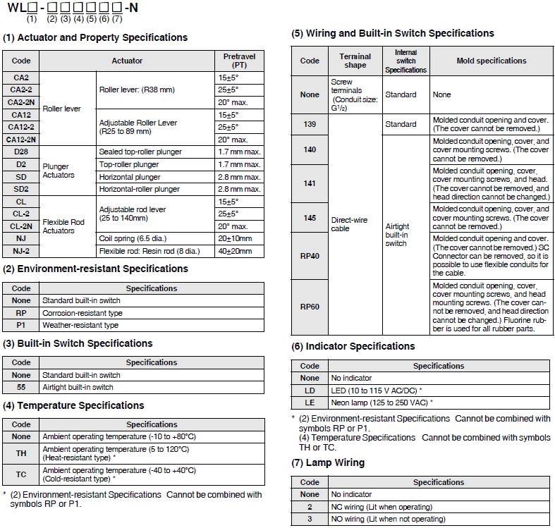
Model Number Legend (Not all combinations are possible. Ask your OMRON representative for details.)
Basic models
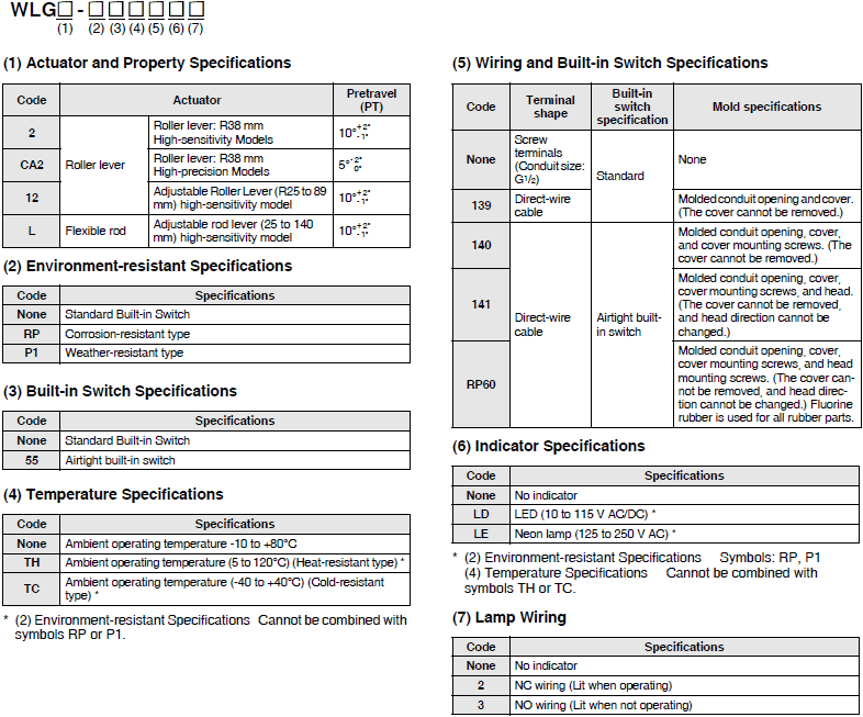
High-sensitivity and High-precision Models
Ordering Information
Roller Lever
| Appear- ance |
Actuator | Terminal shape |
Built-in switch specification/ Temperature Specifications |
Pretravel (PT) |
Without operation indicator |
With operation indicator | |
|---|---|---|---|---|---|---|---|
| Indicator | LED | ||||||
| Model | Wiring Specifications |
Model | |||||
 |
Roller lever: R38 mm |
Screw terminals (Conduit size: G1/2) |
Heat-resistant type |
15±5° | WLCA2-TH-N | — | — |
| 25±5° | WLCA2-2TH-N | — | — | ||||
| 20° max. | WLCA2-2NTH-N | — | — | ||||
| 10°+2°,-1° | WLG2-TH | — | — | ||||
| 5°+2°, 0° | WLGCA2-TH | — | — | ||||
| Cold-resistant type |
15±5° | WLCA2-TC-N | — | — | |||
| 25±5° | WLCA2-2TC-N | — | — | ||||
| 20° max. | WLCA2-2NTC-N | — | — | ||||
| 10°+2°,-1° | WLG2-TC | — | — | ||||
| 5°+2°, 0° | WLGCA2-TC | — | — | ||||
| Corrosion- resistant type |
15±5° | WLCA2-RP-N | — | — | |||
| 10°+2°,-1° | WLG2-RP | — | — | ||||
| 5°+2°, 0° | WLGCA2-RP | — | — | ||||
| Weather- resistant type |
15±5° | WLCA2-P1-N | — | — | |||
| 10°+2°,-1° | WLG2-P1 | — | — | ||||
| Direct- wire cable |
Coolant- resistant type |
15±5° | WLCA2-RP60-N | NC wiring | WLCA2-RP60LD2-N | ||
| NO wiring | WLCA2-RP60LD3-N | ||||||
| 25±5° | WLCA2-2RP60-N | NC wiring | WLCA2-2RP60LD2-N | ||||
| NO wiring | WLCA2-2RP60LD3-N | ||||||
| 10°+2°,-1° | WLG2-RP60 | NC wiring | WLG2-RP60LD2 | ||||
| NO wiring | WLG2-RP60LD3 | ||||||
| 5°+2°, 0° | WLGCA2-RP60 | NC wiring | WLGCA2-RP60LD2 | ||||
| NO wiring | WLGCA2-RP60LD3 | ||||||
| Corrosion- resistant type |
15±5° | WLCA2-RP40-N | — | — | |||
| Molded terminal -139 |
15±5° | WLCA2-139-N | NC wiring | WLCA2-139LD2-N | |||
| NO wiring | WLCA2-139LD3-N | ||||||
| 25±5° | WLCA2-2139-N | NC wiring | WLCA2-2139LD2-N | ||||
| NO wiring | WLCA2-2139LD3-N | ||||||
| 20° max. | WLCA2-2N139-N | — | — | ||||
| 10°+2°,-1° | WLG2-139 | NO wiring | WLG2-139LD3 | ||||
| 5°+2°, 0° | WLGCA2-139 | NC wiring | WLGCA2-139LD2 | ||||
| NO wiring | WLGCA2-139LD3 | ||||||
| Molded terminal -140 |
15±5° | WLCA2-140-N | — | — | |||
| 20° max. | WLCA2-2N140-N | — | — | ||||
| 10°+2°,-1° | WLG2-140 | NC wiring | WLG2-140LD2 * | ||||
| NO wiring | WLG2-140LD3 * | ||||||
| Molded terminal -141 |
15±5° | WLCA2-141-N | NC wiring | WLCA2-141LD2-N | |||
| NO wiring | WLCA2-141LD3-N | ||||||
| 10°+2°,-1° | WLG2-141 | NC wiring | WLG2-141LD2 | ||||
| NO wiring | WLG2-141LD3 | ||||||
| 5°+2°, 0° | WLGCA2-141 | NO wiring | WLGCA2-141LD3 | ||||
 |
Adjustable roller lever (R25 to 89 mm) |
Screw terminals (Conduit size: G1/2) |
Heat-resistant type |
15±5° | WLCA12-TH-N | ─ | ─ |
| 25±5° | WLCA12-2TH-N | ─ | ─ | ||||
| 20° max. | WLCA12-2NTH-N | ─ | ─ | ||||
| 10°+2°,-1° | WLG12-TH | ─ | ─ | ||||
| Cold-resistant type |
15±5° | WLCA12-TC-N | ─ | ─ | |||
| 25±5° | WLCA12-2TC-N | ─ | ─ | ||||
| 20° max. | WLCA12-2NTC-N | ─ | ─ | ||||
| 10°+2°,-1° | WLG12-TC | ─ | ─ | ||||
| Corrosion- resistant type |
15±5° | WLCA12-RP-N | ─ | ─ | |||
| 10°+2°,-1° | WLG12-RP | ─ | ─ | ||||
| Weather- resistant type |
15±5° | WLCA12-P1-N | ─ | ─ | |||
| 10°+2°,-1° | WLG12-P1 | ─ | ─ | ||||
| Direct- wire cable |
Coolant- resistant type |
15±5° | WLCA12-RP60-N | ─ | ─ | ||
| Molded terminal -139 |
15±5° | WLCA12-139-N | ─ | ─ | |||
| Molded terminal -140 |
15±5° | WLCA12-140-N | ─ | ─ | |||
* Ask your OMRON representative for details on Two-core switches.
Plunger
| Appear- ance |
Actuator | Terminal shape | Built-in switch specification/ Temperature Specifications |
Pretravel (PT) |
Without operation indicator |
|---|---|---|---|---|---|
| Model | |||||
 |
Sealed top-roller plunger |
Screw terminals (Conduit size: G1/2) |
Heat-resistant type | 1.7 mm max. |
WLD28-TH-N |
| Cold-resistant type | WLD28-TC-N | ||||
| Corrosion-resistant type | WLD28-RP-N | ||||
| Direct-wire cable | Coolant-resistant type | WLD28-RP60-N | |||
| Molded terminal -139 | WLD28-139-N | ||||
| Molded terminal -140 | WLD28-140-N | ||||
 |
Top-roller plunger |
Screw terminals (Conduit size: G1/2) |
Heat-resistant type | WLD2-TH-N | |
| Direct-wire cable | Coolant-resistant type | WLD2-RP60-N | |||
| Molded terminal -139 | WLD2-139-N | ||||
 |
Horizontal plunger |
Screw terminals (Conduit size: G1/2) |
Heat-resistant type | 2.8 mm max. |
WLSD-TH-N |
| Cold-resistant type | WLSD-TC-N | ||||
| Corrosion-resistant type | WLSD-RP-N | ||||
| Direct-wire cable | Coolant-resistant type | WLSD-RP60-N | |||
| Molded terminal -139 | WLSD-139-N | ||||
 |
Horizontal- roller plunger |
Screw terminals (Conduit size: G1/2) |
Heat-resistant type | WLSD2-TH-N | |
| Cold-resistant type | WLSD2-TC-N | ||||
| Corrosion-resistant type | WLSD2-RP-N | ||||
| Direct-wire cable | Coolant-resistant type | WLSD2-RP60-N | |||
| Molded terminal -139 | WLSD2-139-N | ||||
| Molded terminal -140 | WLSD2-140-N |
Flexible Rod
| Appear- ance |
Actuator | Terminal shape | Built-in switch specification/ Temperature Specifications |
Pretravel (PT) |
Without operation indicator |
|---|---|---|---|---|---|
| Model | |||||
 |
Coil spring (6.5 dia.) |
Screw terminals (Conduit size: G1/2) |
Heat-resistant type | 20±10mm | WLNJ-TH-N |
| Cold-resistant type | WLNJ-TC-N | ||||
| Corrosion-resistant type | WLNJ-RP-N | ||||
| Direct-wire cable | Coolant-resistant type | WLNJ-RP60-N | |||
| Molded terminal -139 | WLNJ-139-N | ||||
| Molded terminal -140 | WLNJ-140-N | ||||
 |
Resin rod (8 dia.) |
Screw terminals (Conduit size: G1/2) |
Corrosion-resistant type | 40±20mm | WLNJ-2RP-N |
| Direct-wire cable | Coolant-resistant type | 40±20mm | WLNJ-2RP60-N | ||
| Molded terminal -139 | WLNJ-2139-N | ||||
| Molded terminal -140 | WLNJ-2140-N | ||||
 |
Adjustable rod lever (25 to 140 mm) |
Screw terminals (Conduit size: G1/2) |
Heat-resistant type | 15±5° | WLCL-TH-N |
| 25±5° | WLCL-2TH-N | ||||
| 20° max. | WLCL-2NTH-N | ||||
| 10°+2°,-1° | WLGL-TH | ||||
| Cold-resistant type | 15±5° | WLCL-TC-N | |||
| 25±5° | WLCL-2TC-N | ||||
| 20° max. | WLCL-2NTC-N | ||||
| 10°+2°,-1° | WLGL-TC | ||||
| Corrosion-resistant type | 15±5° | WLCL-RP-N | |||
| 10°+2°,-1° | WLGL-RP | ||||
| Weather-resistant type | 15±5° | WLCL-P1-N | |||
| 10°+2°,-1° | WLGL-P1 | ||||
| Direct-wire cable | Coolant-resistant type | 15±5° | WLCL-RP60-N | ||
| Molded terminal -139 | 15±5° | WLCL-139-N | |||
| Molded terminal -140 | 15±5° | WLCL-140-N |
Spatter-prevention Switches
Model Number Structure
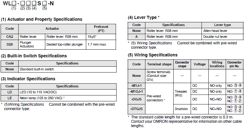
Model Number Legend (Not all combinations are possible. Ask your OMRON representative for details.)
Basic models
High-sensitivity and High-precision Models
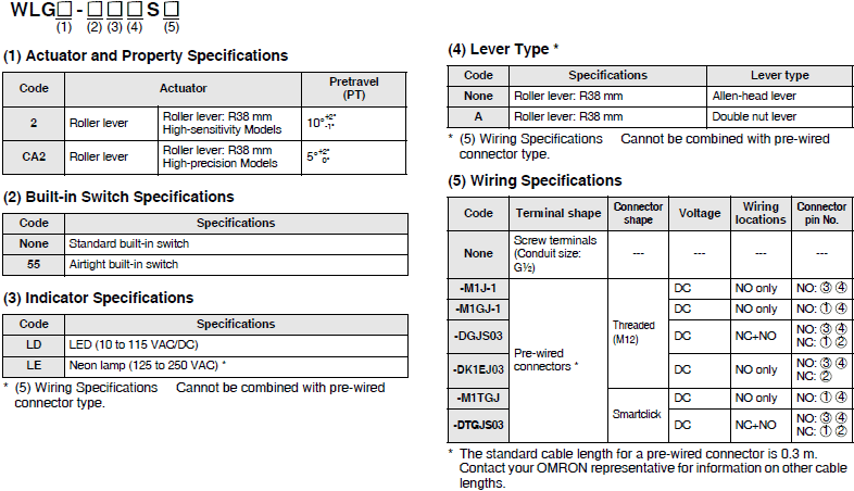
Ordering Information
Roller Lever
Standard built-in switch
Screw terminals
| Appearance | Actuator | Pretravel (PT) | Lever type | With operation indicator * | |
|---|---|---|---|---|---|
| LED | Neon lamp | ||||
| Model | Model | ||||
 |
Roller lever: R38 mm |
15±5° | Double nut Lever | WLCA2-LDAS-N | WLCA2-LEAS-N |
| Allen-head Lever | WLCA2-LDS-N | WLCA2-LES-N | |||
| 10°+2°,-1° | Double nut Lever | WLG2-LDAS | WLG2-LEAS | ||
| Allen-head Lever | WLG2-LDS | WLG2-LES | |||
| 5°+2°, 0° | WLGCA2-LDS | WLGCA2-LES | |||
* The default setting is light-ON when not operating (NO wiring). Turn the lamp holder by 180° to change the setting to light-
ON when operating (NC wiring).
Pre-wired Connectors
| Appear- ance |
Actuator | Pretravel (PT) |
Lever type |
Connector shape |
Usage Voltage |
Wiring locations |
Connector pin No. |
With operation indicator * |
|---|---|---|---|---|---|---|---|---|
| LED | ||||||||
| Wiring Specifications | ||||||||
 |
Roller lever: R38 mm |
15±5° | Allen- head Lever |
Threaded (M12) |
DC | NO only | NO: ③④ | WLCA2-LDS-M1J-1-N |
| NC+NO | NO: ③④ NC: ①② |
WLCA2-LDS-DGJS-N | ||||||
| 10°+2°,-1° | NO: ③④ NC: ①② |
WLG2-LDS-DGJS03 | ||||||
| NO only | NO: ③④ NC: ② |
WLG2-LDS-DK1EJ03 | ||||||
| NO: ③④ | WLG2-LDS-M1J-1 | |||||||
| NO: ①④ | WLG2-LDS-M1GJ-1 | |||||||
| 5°+2°, 0° | NO: ③④ | WLGCA2-LDS-M1J-1 | ||||||
| NO: ①④ | WLGCA2-LDS-M1GJ-1 | |||||||
| 15±5° | Smartclick | NC+NO | NO: ③④ NC: ①② |
WLCA2-LDS-DTGJS-N | ||||
| 10°+2°,-1° | NO only | NO: ①④ | WLG2-LDS-DTGJS03 |
* The default setting is light-ON when not operating (NO wiring). Turn the lamp holder by 180° to change the setting to light-
ON when operating (NC wiring). (However, Three-core and Four-core Switches cannot be switched to light-ON when
operating (NC wiring)
Airtight Built-in Switch
Pre-wired Connector types
| Appear- ance |
Actuator | Pretravel (PT) |
Lever type |
Connector shape |
Usage Voltage |
Wiring locations |
Connector pin No. |
With operation indicator * |
|---|---|---|---|---|---|---|---|---|
| LED | ||||||||
| Model | ||||||||
 |
Roller lever: R38 mm |
10° +2°,-1° |
Allen- head Lever |
Threaded (M12) |
DC | NO only | NO: ③④ | WLG2-55LDS-M1J-1 |
| NO: ①④ | WLG2-55LDS-M1GJ-1 | |||||||
| NC+NO | NO: ③④ NC: ①② |
WLG2-55LDS-DGJS03 | ||||||
| Smartclick | NO: ③④ NC: ①② |
WLG2-55LDS-M1TGJ |
* The default setting is light-ON when not operating (NO wiring). Turn the lamp holder by 180° to change the setting to light-
ON when operating (NC wiring). (However, Three-core and Four-core Switches cannot be switched to light-ON when
operating (NC wiring).)
Plunger Actuators
Standard built-in switch
Screw terminals
| Appearance | Actuator | Pretravel (PT) | With operation indicator * | |
|---|---|---|---|---|
| LED | Neon lamp | |||
| Model | Model | |||
 |
Sealed top-roller plunger | 1.7 mm max. | WLD28-LDS-N | WLD28-LES-N |
* The default setting is light-ON when not operating (NO wiring). Turn the lamp holder by 180° to change the setting to light-
ON when operating (NC wiring).
Pre-wired Connectors
| Appear- ance |
Actuator | Pretravel (PT) |
Connector shape |
Voltage | Wiring locations |
Connector pin No. |
With operation indicator * |
|---|---|---|---|---|---|---|---|
| LED | |||||||
| Model | |||||||
 |
Sealed top-roller plunger |
1.7 mm max. |
Threaded (M12) |
DC | NO only | NO: ③④ | WLD28-LDS-M1J-1-N |
| DC | NO only | NO: ①④ | WLD28-LDS-M1GJ-1-N | ||||
| DC | NC+NO | NO: ③④ NC: ①② |
WLD28-LDS-DGJS-N | ||||
| Smartclick | DC | NC+NO | NO: ③④ NC: ①② |
WLD28-LDS-DTGJS-N |
Note: The standard cable length for a pre-wired connector is 0.3 m. Contact your OMRON representative for information on
other cable lengths.
* The default setting is light-ON when not operating (NO wiring). Turn the lamp holder by 180° to change the setting to light-
ON when operating (NC wiring). (However, Three-core and Four-core Switches cannot be switched to light-ON when
operating (NC wiring).)
Long-life Switches
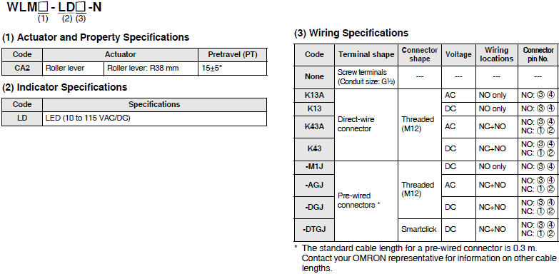
Model Number Structure
Model Number Legend (Not all combinations are possible. Ask your OMRON representative for details.)
Basic models
High-sensitivity and High-precision Switches
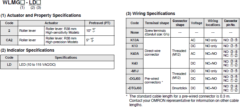
Ordering Information
Roller Lever
Screw terminals
| Appearance | Actuator | Pretravel (PT) | With operation indicator * |
|---|---|---|---|
| LED | |||
| Model | |||
 |
Roller lever: R38 mm | 15±5° | WLMCA2-LD-N |
 |
10°+2°,-1° | WLMG2-LD | |
| 5°+2°, 0° | WLMGCA2-LD |
* The default setting is light-ON when not operating (NO wiring). Turn the lamp holder by 180° to change the setting to light-
ON when operating (NC wiring).
Direct-wire connector
| Appearance | Actuator | Pretravel (PT) | Voltage | Wiring locations |
Connector pin No. |
With operation indicator * |
|---|---|---|---|---|---|---|
| LED | ||||||
| Model | ||||||
 |
Roller lever: R38 mm |
15±5° | AC | NO only | NO: ③④ | WLMCA2-LDK13A-N |
| NC+NO | NO: ③④ NC: ①② |
WLMCA2-LDK43A-N | ||||
| DC | NO only | NO: ③④ | WLMCA2-LDK13-N | |||
| NC+NO | NO: ③④ NC: ①② |
WLMCA2-LDK43-N | ||||
 |
10°+2°,-1° | AC | NO only | NO: ③④ | WLMG2-LDK13A | |
| NC+NO | NO: ③④ NC: ①② |
WLMG2-LDK43A | ||||
| DC | NO only | NO: ③④ | WLMG2-LDK13 | |||
| NC+NO | NO: ③④ NC: ①② |
WLMG2-LDK43 | ||||
| 5°+2°, 0° | AC | NO only | NO: ③④ | WLMGCA2-LDK13A | ||
| NC+NO | NO: ③④ NC: ①② |
WLMGCA2-LDK43A | ||||
| DC | NO only | NO: ③④ | WLMGCA2-LDK13 | |||
| NC+NO | NO: ③④ NC: ①② |
WLMGCA2-LDK43 |
* The default setting is light-ON when not operating (NO wiring). Turn the lamp holder by 180° to change the setting to light-
ON when operating (NC wiring). (However, Three-core and Four-core Switches cannot be switched to light-ON when
operating (NC wiring).)
Pre-wired connectors
| Appear- ance |
Actuator | Pretravel (PT) |
Voltage | Connector shape |
Wiring locations |
Connector pin No. |
With operation indicator * |
|---|---|---|---|---|---|---|---|
| LED | |||||||
| Model | |||||||
 |
Roller lever: R38 mm |
15±5° | AC | Threaded (M12) |
NO only | NO: ③④ | WLMCA2-LD-M1J-N |
| NC+NO | NO: ③④ NC: ①② |
WLMCA2-LD-AGJ-N | |||||
| DC | NO: ③④ NC: ①② |
WLMCA2-LD-DGJ-N | |||||
| Smartclick | NC+NO | NO: ③④ NC: ①② |
WLMCA2-LD-DTGJ-N | ||||
 |
10° +2°,-1° |
Threaded (M12) |
NO only | NO: ③④ | WLMG2-LD-M1J | ||
| NC+NO | NO: ③④ NC: ①② |
WLMG2-LD-DGJ03 | |||||
| Smartclick | NO: ③④ NC: ①② |
WLMG2-LD-DTGJ03 | |||||
| 5°+2°, 0° | Threaded (M12) |
NO only | NO: ③④ | WLMGCA2-LD-M1J | |||
| Smartclick | NC+NO | NO: ③④ NC: ①② |
WLMGCA2-LD-DTGJ03 |
Note: The standard cable length for a pre-wired connector is 0.3 m. Contact your OMRON representative for information on
other cable lengths.
* The default setting is for light-ON when not operating. Turn the lamp holder by 180° to change the setting to light-ON when
operating. (However, Four-core Switches cannot be switched to light-ON when operating (NC wiring).
Common Accessories (Sold Separately)
Single-item ordering models
Switches without levers, heads, and actuators can be ordered separately. Use by combining with models that are not available as a set. You can also use them as maintenance parts for inventory management.
General-purpose Models
| Actuator | Pretravel (PT) |
Set Model Numbers |
Switches without levers | Heads (with Actuators) |
Actuator * |
|---|---|---|---|---|---|
| Model | Model | Model | |||
| Roller lever: R38 mm | 15±5° | WLCA2-N | WLRCA2-N | WL-1H1100-N | WL-1A100 |
| 25±5° | WLCA2-2-N | WLRCA2-2-N | WL-3H1100-N | ||
| 20° max. | WLCA2-2N-N | WLRCA2-2N-N | WL-1H1100-N | ||
| 10°+2°,-1° | WLG2 | — | WL-2H1100-K * | ||
| Adjustable roller lever (R25 to 89 mm) |
15±5° | WLCA12-N | WLRCA2-N | WL-1H2100-N | WL-2A100 |
| 25±5° | WLCA12-2-N | WLRCA2-2-N | WL-3H2100-N | ||
| 20° max. | WLCA12-2N-N | WLRCA2-2N-N | WL-1H2100-N | ||
| 10°+2°,-1° | WLG12 | WLRG2 | WL-2H2100-K * | ||
| Adjustable rod lever: (25 to 140mm) |
15±5° | WLCL-N | WLRCL-N | WL-4H4100-N | WL-4A100 |
| 25±5° | WLCL-2-N | WLRCA2-2-N | WL-3H4100-N | ||
| 20° max. | WLCL-2N-N | WLRCA2-2N-N | WL-1H4100-N | ||
| 10°+2°,-1° | WLGL | WLRG2 | WL-2H4100-K * | ||
| Sealed top plunger | 1.7 mm max. | WLD18-N | — | WL-7H100-N | — |
| Sealed top-roller plunger | 1.7 mm max. | WLD28-N | — | WL-7H400-N | — |
| Sealed top-ball plunger | 1.7 mm max. | WLD38-N | — | WL-7H300-N | — |
| Horizontal plunger | 2.8 mm max. | WLSD-N | — | WL-8H100-N | — |
| Horizontal-roller plunger | 2.8 mm max. | WLSD2-N | — | WL-8H200-N | — |
| Horizontal-ball plunger | 2.8 mm max. | WLSD3-N | — | WL-8H300-N | — |
| Coil spring (6.5 dia.) | 20±10 mm | WLNJ-N | — | WL-9H100-N | — |
| Coil spring (4.8 dia.) | 20±10 mm | WLNJ-30-N | — | WL-9H200-N | — |
| Flexible rod: Resin rod (8 dia.) |
40±20 mm | WLNJ-2-N | — | WL-9H300-N | — |
| Flexible rod: Steel wire (1 dia.) |
40±20 mm | WLNJ-S2-N | — | WL-9H400-N | — |
| Fork Lock Lever A | 55° max. | WLCA32-41-N | WLRCA32-N | WL-5H5100-N | WL-5A100 |
| Fork Lock Lever B | 55° max. | WLCA32-42-N | WL-5H5102-N | WL-5A102 | |
| Fork Lock Lever C | 55° max. | WLCA32-43-N | WL-5H5104-N | WL-5A104 | |
| Fork Lock Lever D | 55° max. | WLCA32-44-N | WL-5H5104-N | WL-5A104 |
* The WL-2H1100-K, WL-2H2100-K, and WL-2H4100-K correspond with each set model WLG[], the design of which was
changed in April 2019.
Please inquire if you desire a single-item head manufactured before the design change. On products that underwent the
design change in April 2019, the front of the switch box cover at the bottom front has a protruding shape, and on earlier
products has a depressed shape. 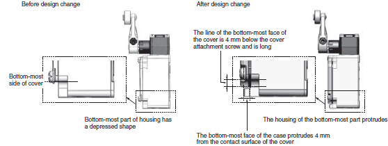
Spatter-prevention Models
| Actuator | Lever type | Indicator | Pretravel (PT) |
Set Model Numbers | Switches without levers |
Actuator * |
|---|---|---|---|---|---|---|
| Model | Model | |||||
| Roller lever: R38 mm |
Double nut lever |
LED | 15±5° | WLCA2-LDAS-N | WLRCA2-LDS-N | WL-1A105S |
| Neon lamp | WLCA2-LEAS-N | WLRCA2-LES-N | ||||
| LED | 10°+2°,-1° | WLG2-LDAS | WLRG2-LDS | |||
| Allen-head lever |
LED | 15±5° | WLCA2-LDS-N | WLRCA2-LDS-N | WL-1A103S | |
| Neon lamp | WLCA2-LES-N | WLRCA2-LES-N | ||||
| LED | 10°+2°,-1° | WLG2-LDS | WLRG2-LDS |
* The actuator is identical for the WL and WL-N models.
Connector (Conduit size: JIS B0202G1/2)
| Actuator | Application/ Specifications |
External diameter of cable | Model | Applicable limit switch models |
|
|---|---|---|---|---|---|
| min. | max. | ||||
 |
Cabtire cable (Metal, with O-ring) |
5.5 dia. | 7.5 dia. | SC-1M | WL[]-N WLG[]Wiring Specifications: Screw terminals |
| 7.5 dia. | 9.5 dia. | SC-2M | |||
| 11 dia. | 13 dia. | SC-3M | |||
| 12 dia. | 14 dia. | SC-4M | |||
| 9 dia. | 11 dia. | SC-5M | |||
 |
Cabtire cable (Metal) |
5.5 dia. | 7.5 dia. | SC-21 | |
| 7.5 dia. | 9.5 dia. | SC-22 | |||
| 11 dia. | 13 dia. | SC-23 | |||
| 12 dia. | 14 dia. | SC-24 | |||
| 9 dia. | 11 dia. | SC-25 | |||
 |
Cabtire cable (Resin) |
7.5 dia. | 9 dia. | SC-6 | |
 |
8.5 dia. | 10.5 dia. | SC-P2 | ||
Note: Please use sealling tape with SC Connectors. SC-1M to SC-5M, however, are provided with an O-ring (NBR) and therefore sealing tape is not necessary to ensure a proper seal. The SC-6 and SC-P2 models are made of resin. If higher sealing performance is required, use one of SC-1M to SC-5M, which have metal connectors.
FA Connectors
| Model | Number of conductors |
Voltage specification |
Size of conduit | Size of crimp terminal |
Applicable model |
|---|---|---|---|---|---|
| SC-2F | 2 | 125 VDC | JIS B0202G1/2 | M4 | WL-N, WLG |
| SC-2FAD | 2 | 250 VDC | |||
| SC-4F4D | 4 | 125 VDC | |||
| SC-4F4AD | 4 | 250 VDC |
Sensor I/O connectors
| Actuator | AC/DC type |
Number of cable cores |
Cable length (m) |
Cable model | Compatible model |
|---|---|---|---|---|---|
M12 Screw (Straight) |
for AC | 2 | 2 | XS2F-A421-DB0-F | WL[]-[]K13A-N WLG[]-[]K13A |
| 5 | XS2F-A421-GB0-F | ||||
| 4 | 2 | XS2F-A421-D90-F | WL[]-[]K43A-N WL[]-[]-AGJ-N WLG[]-[]K43A WLG[]-[]-AGJ03 |
||
| 5 | XS2F-A421-G90-F | ||||
| for DC | 2 | 2 | XS2F-D421-DD0 | WL[]-[]K13-N WL[]-[]-M1J-N WLG[]-[]K13 WLG[]-[]-M1J |
|
| 5 | XS2F-D421-GD0 | ||||
| 2 | XS2F-D421-DA0-F | WL[]-[]-M1GJ[]-N WLG[]-[]-M1GJ[] |
|||
| 5 | XS2F-D421-GA0-F | ||||
| 4 | 2 | XS2F-D421-D80-F | WL[]-[]K43-N WL[]-[]-M1JB-N WL[]-[]-DGJ-N WL[]-[]-DK1EJ-N WLG[]-[]K43 WLG[]-[]-M1JB WLG[]-[]-DGJ03 WLG[]-[]-DK1EJ03 |
||
| 5 | XS2F-D421-G80-F | ||||
| M12 Smartclick (Straight)  |
for DC | 4 | 2 | XS5F-D421-D80-F | WL[]-[]-M1TJ-N WL[]-[]-M1TGJ-N WL[]-[]-M1TJB-N WL[]-[]-DTGJ-N WL[]-[]-DTK1EJ-N WLG[]-[]-M1TJ WLG[]-[]-M1TGJ WLG[]-[]-M1TJB WLG[]-[]-DTGJ03 WLG[]-[]-DTK1EJ03 |
| 5 | XS5F-D421-G80-F |
Note: For details, refer to the data sheet for XS2 Round Water-resistant Connectors (M12 Threads) or XS5 Round Water-
resistant Connectors (M12 Smartclick).
| Type | Compatible model | Remarks | Model | |||
|---|---|---|---|---|---|---|
| Cover with indicator lamps *1 |
WL-N | General-purpose models Long-life models (Basic models, High- sensitivity Switches) |
Indicator *1 |
LED | Color: Red | WL-LD-N |
| Neon lamp | Color: Orange | WL-LE-N | ||||
| Spatter Prevention models | LED | Color: Red | WL-LDS-N | |||
| Neon lamp | Color: Orange | WL-LES-N | ||||
| WLG | General-purpose models | Indicator | LED | Color: Red | WL-LD-K *2 | |
| Long-life models | Neon lamp | Color: Orange | WL-LE-K *2 | |||
| Spatter Prevention models | LED | Color: Red | WL-LDS-K *2 | |||
| Neon lamp | Color: Orange | WL-LES-K *2 | ||||
| Terminal Plate | WL[]-N | Change from bipolar to monopolar (contact C). |
WL-N TERMINAL PLATE |
|||
| Side mounting plate |
WL[]-2N-N | — | WLN-P001 | |||
*1. The default setting is for light-ON when not operating. Turn the lamp holder by 180° to change the setting to light-ON when operating.
*2. The WL-LD-K, WL-LE-K, WL-LDS-K, and WL-LES-K correspond with each set model WLG[], the design of which was
changed in April 2019. Refer to the above for details.
Specifications | Limit Switches – WL-N / WL
General-purpose Switches
Ratings
Screw terminals
Without Operation Indicator
Basic models (WL-N)
| Ratings | Non-inductive load (A) | Inductive load (A) | |||||||
|---|---|---|---|---|---|---|---|---|---|
| Basic models (WL-N) | Basic models (WL-N) | ||||||||
| Resistive load | Lamp load | Inductive load | Motor load | ||||||
| Voltage (V) | NC | NO | NC | NO | NC | NO | NC | NO | |
| AC | 125 | 10 | 3 | 1.5 | 10 | 5 | 2.5 | ||
| 250 | 10 | 2 | 1 | 10 | 3 | 1.5 | |||
| 500 | 10 | 1.5 | 0.8 | 3 | 1.5 | 0.8 | |||
| DC | 8 | 10 | 6 | 3 | 10 | 6 | |||
| 14 | 10 | 6 | 3 | 10 | 6 | ||||
| 30 | 6 | 4 | 3 | 6 | 4 | ||||
| 125 | 0.8 | 0.2 | 0.2 | 0.8 | 0.2 | ||||
| 250 | 0.4 | 0.1 | 0.1 | 0.4 | 0.1 | ||||
High-sensitivity and High-precision models (WLG)
| Ratings | Non-inductive load (A) | ||
|---|---|---|---|
| High-sensitivity and High-precision models (WLG) | |||
| Resistive load | |||
| Voltage (V) | NC | NO | |
| AC | 125 | 5 | |
| 250 | 5 | ||
| DC | 125 | 0.4 | |
| 250 | 0.2 | ||
With Operation Indicator (LED)
Basic models (WL-N)
| Ratings | Non-inductive load (A) | Inductive load (A) | |||||||
|---|---|---|---|---|---|---|---|---|---|
| Basic models (WL-N) | Basic models (WL-N) | ||||||||
| Resistive load | Lamp load | Inductive load | Motor load | ||||||
| Voltage (V) | NC | NO | NC | NO | NC | NO | NC | NO | |
| AC | 115 | 10 | 3 | 1.5 | 10 | 5 | 2.5 | ||
| DC | 12 | 10 | 6 | 3 | 10 | 6 | |||
| 24 | 6 | 4 | 3 | 6 | 4 | ||||
| 48 | 3 | 2 | 1.5 | 3 | 0.2 | ||||
| 115 | 0.8 | 0.2 | 0.8 | 0.1 | |||||
High-sensitivity and High-precision models (WLG)
| Ratings | Non-inductive load (A) | ||
|---|---|---|---|
| High-sensitivity and High-precision models (WLG) | |||
| Resistive load | |||
| Voltage (V) | NC | NO | |
| AC | 115 | 5 | |
| DC | 115 | 0.4 | |
With Operation Indicators (Neon Lamps)
Basic models (WL-N)
| Ratings | Non-inductive load (A) | Inductive load (A) | |||||||
|---|---|---|---|---|---|---|---|---|---|
| Basic models (WL-N) | Basic models (WL-N) | ||||||||
| Resistive load | Lamp load | Inductive load | Motor load | ||||||
| Voltage (V) | NC | NO | NC | NO | NC | NO | NC | NO | |
| AC | 125 | 10 | 3 | 1.5 | 10 | 5 | 2.5 | ||
| 250 | 10 | 2 | 1 | 10 | 3 | 1.5 | |||
High-sensitivity and High-precision models (WLG)
| Ratings | Non-inductive load (A) | ||
|---|---|---|---|
| High-sensitivity and High-precision models (WLG) | |||
| Resistive load | |||
| Voltage (V) | NC | NO | |
| AC | 125 | 5 | |
| 250 | 5 | ||
Note: 1. The above figures are for steady-state currents.
2. Inductive loads have a power factor of 0.4 min. (AC) and a time constant of 7 ms max. (DC).
3. A lamp load has an inrush current of 10 times the steady-state current.
4. A motor load has an inrush current of 6 times the steady-state current.
Allowable Inrush Current/Minimum Applicable Load
| Operating characteristics type | Basic models (WL-N) | High-sensitivity and High-precision models (WLG) |
|
|---|---|---|---|
| Inrush current | NC | 30 A max. | 15 A max. |
| NO | 20 A max. | 10 A max. | |
| Minimum applicable load | 5 VDC 1 mA, resistive load, P level | 5 VDC 1 mA, resistive load, P level | |
Operation Indicator
| Operation indicator type | LED | Neon lamp |
|---|---|---|
| Rated voltage | 10 to 115 VAC/DC | 125 to 250 VAC |
| Leakage current (Reference value) |
Approx. 0.4 mA at 10 VAC/DC Approx. 0.5 mA at 115 VAC/DC |
Approx. 0.6 mA at 125 VAC Approx. 1.9 mA at 250 VAC |
Direct-wired connector and Pre-wired Connector Type
Connector DC Specifications: With Operation Indicators (LEDs)
Basic models (WL-N)
| Ratings | Non-inductive load (A) | Inductive load (A) | |||||||
|---|---|---|---|---|---|---|---|---|---|
| Basic models (WL-N) | Basic models (WL-N) | ||||||||
| Resistive load | Lamp load | Inductive load | Motor load | ||||||
| Voltage (V) | NC | NO | NC | NO | NC | NO | NC | NO | |
| DC | 12 | 3 | 3 | 3 | 3 | ||||
| 24 | 3 | 3 | 3 | 3 | |||||
| 48 | 4 | 2 | 1.5 | 3 | 2 | ||||
| 115 | 0.8 | 0.2 | 0.2 | 0.8 | 0.2 | ||||
High-sensitivity and High-precision models (WLG)
| Ratings | Non-inductive load (A) | ||
|---|---|---|---|
| High-sensitivity and High-precision models (WLG) | |||
| Resistive load | |||
| Voltage (V) | NC | NO | |
| DC | 115 | 0.4 | |
Connector AC Specifications: With Operation Indicators (LEDs)
Basic models (WL-N)
| Ratings | Non-inductive load (A) | Inductive load (A) | |||||||
|---|---|---|---|---|---|---|---|---|---|
| Basic models (WL-N) | Basic models (WL-N) | ||||||||
| Resistive load | Lamp load | Inductive load | Motor load | ||||||
| Voltage (V) | NC | NO | NC | NO | NC | NO | NC | NO | |
| AC | 115 | 3 | 3 | 1.5 | 3 | 3 | 2.5 | ||
High-sensitivity and High-precision models (WLG)
| Ratings | Non-inductive load (A) | ||
|---|---|---|---|
| High-sensitivity and High-precision models (WLG) | |||
| Resistive load | |||
| Voltage (V) | NC | NO | |
| AC | 115 | 3 | |
Note: 1. The above figures are for steady-state currents.
2. Inductive loads have a power factor of 0.4 min. (AC) and a time constant of 7 ms max. (DC).
3. A lamp load has an inrush current of 10 times the steady-state current.
4. A motor load has an inrush current of 6 times the steady-state current.
Minimum Applicable Load
| Operating characteristics type | Basic models (WL-N) | High-sensitivity and High-precision models (WLG) |
|---|---|---|
| Minimum applicable load | 5 VDC 1 mA, resistive load, P level | 5 VDC 1 mA, resistive load, P level |
Operation Indicator
| Operation indicator type | LED | Neon lamp |
|---|---|---|
| Rated voltage | 10 to 115 VAC/DC | 125 to 250 VAC |
| Leakage current (Reference value) |
Approx. 0.4 mA at 10 VAC/DC Approx. 0.5 mA at 115 VAC/DC |
Approx. 0.6 mA at 125 VAC Approx. 1.9 mA at 250 VAC |
Characteristics
| Operating characteristics type | Basic models (WL-N) | High-sensitivity and High-precision models (WLG) |
|
|---|---|---|---|
| Permissible operating frequency |
Mechanical | 120 operations/minute | |
| Electrical | 30 operations/minute | ||
| Rated frequency | 50/60 Hz | ||
| Permissible operating speed | 1 mm/s to 1 m/s (in case of WLCA2-N) | ||
| Insulation resistance | 100 MΩ min. (at 500 VDC) | ||
| Contact resistance | 25 mΩ max. (initial value for the built-in switch) | ||
| Vibration resistance | Malfunction | 10 to 55 Hz, 1.5-mm double amplitude | |
| Shock | Destruction | 1,000 m/s2 max. | |
| Malfunction | 300 m/s2 max. *2 | ||
| Durability *1 | Mechanical | 15,000,000 operations min. | 10,000,000 operations min. |
| Electrical | 750,000 operations min. (3 A at 250 VAC, resistive load), but for high- precision models: *3 |
500,000 operations min. (3 A at 250 VAC, resistive load), but for high- precision models: *3 |
|
| Ambient operating temperature | -10 to +80°C (with no icing) | ||
| Ambient operating humidity | 35 to 95%RH | ||
| Degree of protection | IP67 | ||
| Weight | Approx. 255 g (in case of WLCA2-N) | Approx. 270 g (in case of WLGCA2) | |
Note: The above figures are initial values.
*1. The values are calculated at an operating temperature of +5°C to +35°C, and an operating humidity of 40% to 70%RH.
Contact your OMRON sales representative for more detailed information on other operating environments.
*2. Except Switches with Flexible Rod Actuators.
*3. In case of Screw terminals without operation indicators.
| Operating characteristics type | Basic models (WL-N) | High-sensitivity and High-precision models (WLG) |
|||
|---|---|---|---|---|---|
| Wiring Specifications | Screw terminals |
Direct-wire connector/ Pre-wired Connector Models |
Screw terminals |
Direct-wire connector/ Pre-wired Connector Models |
|
| Dielectric strength |
Between terminals of the same polarity |
1,000 VAC, 50/60 Hz for 1 min * |
600 VAC, 50/60 Hz for 1 min * |
600 VAC, 50/60 Hz for 1 min * |
600 VAC, 50/60 Hz for 1 min * |
| Between current- carrying metal part and ground |
2,200 VAC, 50/60 Hz for 1 min |
1,500 VAC, 50/60 Hz for 1 min |
1,500 VAC, 50/60 Hz for 1 min |
1,500 VAC, 50/60 Hz for 1 min |
|
| Between each terminal and non- current-carrying metal part |
2,200 VAC, 50/60 Hz for 1 min |
1,500 VAC, 50/60 Hz for 1 min |
1,500 VAC, 50/60 Hz for 1 min |
1,500 VAC, 50/60 Hz for 1 min |
|
* Excluding those with operation indicators.
Environment-resistant Limit Switches
Ratings
Screw terminals/Direct-wire cable
Without Operation Indicator
Basic models (WL-N)
| Ratings | Non-inductive load (A) | Inductive load (A) | |||||||
|---|---|---|---|---|---|---|---|---|---|
| Basic models (WL-N) | Basic models (WL-N) | ||||||||
| Resistive load | Lamp load | Inductive load | Motor load | ||||||
| Voltage (V) | NC | NO | NC | NO | NC | NO | NC | NO | |
| AC | 125 | 10 | 3 | 1.5 | 10 | 5 | 2.5 | ||
| 250 | 10 | 2 | 1 | 10 | 3 | 1.5 | |||
| 500 | 10 | 1.5 | 0.8 | 3 | 1.5 | 0.8 | |||
| DC | 8 | 10 | 6 | 3 | 10 | 6 | |||
| 14 | 10 | 6 | 3 | 10 | 6 | ||||
| 30 | 6 | 4 | 3 | 6 | 4 | ||||
| 125 | 0.8 | 0.2 | 0.2 | 0.8 | 0.2 | ||||
| 250 | 0.4 | 0.1 | 0.1 | 0.4 | 0.1 | ||||
High-sensitivity and High-precision models (WLG)
| Ratings | Non-inductive load (A) | ||
|---|---|---|---|
| High-sensitivity and High-precision models (WLG) | |||
| Resistive load | |||
| Voltage (V) | NC | NO | |
| AC | 125 | 5 | |
| 250 | 5 | ||
| DC | 125 | 0.4 | |
| 250 | 0.2 | ||
With Operation Indicator (LED)
Basic models (WL-N)
| Ratings | Non-inductive load (A) | Inductive load (A) | |||||||
|---|---|---|---|---|---|---|---|---|---|
| Basic models (WL-N) | Basic models (WL-N) | ||||||||
| Resistive load | Lamp load | Inductive load | Motor load | ||||||
| Voltage (V) | NC | NO | NC | NO | NC | NO | NC | NO | |
| AC | 115 | 10 | 3 | 1.5 | 10 | 5 | 2.5 | ||
| DC | 12 | 10 | 6 | 3 | 10 | 6 | |||
| 24 | 6 | 4 | 3 | 6 | 4 | ||||
| 48 | 3 | 2 | 1.5 | 3 | 0.2 | ||||
| 115 | 0.8 | 0.2 | 0.8 | 0.1 | |||||
High-sensitivity and High-precision models (WLG)
| Ratings | Non-inductive load (A) | ||
|---|---|---|---|
| High-sensitivity and High-precision models (WLG) | |||
| Resistive load | |||
| Voltage (V) | NC | NO | |
| AC | 115 | 5 | |
| DC | 115 | 0.4 | |
With Operation Indicators (Neon Lamps)
Basic models (WL-N)
| Ratings | Non-inductive load (A) | Inductive load (A) | |||||||
|---|---|---|---|---|---|---|---|---|---|
| Basic models (WL-N) | Basic models (WL-N) | ||||||||
| Resistive load | Lamp load | Inductive load | Motor load | ||||||
| Voltage (V) | NC | NO | NC | NO | NC | NO | NC | NO | |
| AC | 125 | 10 | 3 | 1.5 | 10 | 5 | 2.5 | ||
| 250 | 10 | 2 | 1 | 10 | 3 | 1.5 | |||
High-sensitivity and High-precision models (WLG)
| Ratings | Non-inductive load (A) | ||
|---|---|---|---|
| High-sensitivity and High-precision models (WLG) | |||
| Resistive load | |||
| Voltage (V) | NC | NO | |
| AC | 125 | 5 | |
| 250 | 5 | ||
Note: 1. The above figures are for steady-state currents.
2. Inductive loads have a power factor of 0.4 min. (AC) and a time constant of 7 ms max. (DC).
3. A lamp load has an inrush current of 10 times the steady-state current.
4. A motor load has an inrush current of 6 times the steady-state current.
Allowable Inrush Current/ Minimum applicable load
| Operating characteristics type | Basic models (WL-N) | High-sensitivity and High-precision models (WLG) |
|
|---|---|---|---|
| Inrush current | NC | 30 A max. | 15 A max. |
| NO | 20 A max. | 10 A max. | |
| Minimum applicable load | 5 VDC 1 mA, resistive load, P level | 5 VDC 1 mA, resistive load, P level | |
Operation Indicator
| Operation indicator type | LED | Neon lamp |
|---|---|---|
| Rated voltage | 10 to 115 VAC/DC | 125 to 250 VAC |
| Leakage current (Reference value) |
Approx. 0.4 mA at 10 VAC/DC Approx. 0.5 mA at 115 VAC/DC |
Approx. 0.6 mA at 125 VAC Approx. 1.9 mA at 250 VAC |
Characteristics
| Operating characteristics type | Basic models (WL-N) | High-sensitivity and High-precision models (WLG) |
|
|---|---|---|---|
| Permissible operating frequency |
Mechanical | 120 operations/minute | |
| Electrical | 30 operations/minute | ||
| Rated frequency | 50/60 Hz | ||
| Permissible operating speed | 1 mm/s to 1 m/s (in case of WLCA2-N) | ||
| Insulation resistance | 100 MΩ min. (at 500 VDC) | ||
| Contact resistance | 25 mΩ or less (default value, built-in switch only) | ||
| Vibration resistance | Malfunction | 10 to 55 Hz, 1.5-mm double amplitude *2 | |
| Shock | Destruction | 1,000 m/s2 max. | |
| Malfunction | 300m/s2 max. *2 | ||
| Durability *1 | Mechanical | 15,000,000 operations min. | 10,000,000 operations min. *3 |
| Electrical | 750,000 operations min. (3 A at 250 VAC, resistive load) *4 |
500,000 operations min. (3 A at 250 VAC, resistive load) *4 |
|
| Ambient operating temperature | -10 to +80°C (with no icing) *5 | ||
| Ambient operating humidity | 35 to 95%RH | ||
| Degree of protection | IP67 | ||
| Weight | Approx. 250 g (for WLCL-TH-N) | Approx. 250 g (for WLCL-TH-N) | |
Note: The above figures are initial values.
*1. The values are calculated at an operating temperature of +5°C to +35°C, and an operating humidity of 40% to 70%RH.
Contact your OMRON sales representative for more detailed information on other operating environments.
*2. Except Switches with Flexible Rod Actuators.
*3. 500,000 operations min. for Weather-resistant models.
*4. In case of models without operation indicators.
*5. For low-temperature models this is -40°C to +40°C (with no icing). For heat-resistant models the range is +5°C to
120°C.
| Operating characteristics type | Basic models (WL-N) | High-sensitivity and High-precision models (WLG) |
|
|---|---|---|---|
| Wiring Specifications | Screw terminals/ Direct-wire cable models |
Screw terminals/ Direct-wire cable models |
|
| Dielectric strength |
Between terminals of the same polarity | 1,000 VAC, 50/60 Hz for 1 min * | 600 VAC, 50/60 Hz for 1 min * |
| Between current-carrying metal part and ground |
2,200 VAC, 50/60 Hz for 1 min | 1,500 VAC, 50/60 Hz for 1 min | |
| Between each terminal and non- current-carrying metal part |
2,200 VAC, 50/60 Hz for 1 min | 1,500 VAC, 50/60 Hz for 1 min | |
* Except models with operation indicators.
Spatter-prevention Switches
Ratings
Screw terminals
With Operation Indicator
Basic models (WL-N)
| Ratings | Non-inductive load (A) | Inductive load (A) | |||||||
|---|---|---|---|---|---|---|---|---|---|
| Basic models (WL-N) | Basic models (WL-N) | ||||||||
| Resistive load | Lamp load | Inductive load | Motor load | ||||||
| Voltage (V) | NC | NO | NC | NO | NC | NO | NC | NO | |
| AC | 115 | 10 | 3 | 1.5 | 10 | 5 | 2.5 | ||
| DC | 12 | 10 | 6 | 3 | 10 | 6 | |||
| 24 | 6 | 4 | 3 | 6 | 4 | ||||
| 48 | 3 | 2 | 1.5 | 3 | 0.2 | ||||
| 115 | 0.8 | 0.2 | 0.8 | 0.1 | |||||
High-sensitivity and High-precision models (WLG)
| Ratings | Non-inductive load (A) | ||
|---|---|---|---|
| High-sensitivity and High-precision models (WLG) | |||
| Resistive load | |||
| Voltage (V) | NC | NO | |
| AC | 115 | 5 | |
| DC | 115 | 0.4 | |
With Operation Indicators (Neon Lamps)
Basic models (WL-N)
| Ratings | Non-inductive load (A) | Inductive load (A) | |||||||
|---|---|---|---|---|---|---|---|---|---|
| Basic models (WL-N) | Basic models (WL-N) | ||||||||
| Resistive load | Lamp load | Inductive load | Motor load | ||||||
| Voltage (V) | NC | NO | NC | NO | NC | NO | NC | NO | |
| AC | 125 | 10 | 3 | 1.5 | 10 | 5 | 2.5 | ||
| 250 | 10 | 2 | 1 | 10 | 3 | 1.5 | |||
High-sensitivity and High-precision models (WLG)
| Ratings | Non-inductive load (A) | ||
|---|---|---|---|
| High-sensitivity and High-precision models (WLG) | |||
| Resistive load | |||
| Voltage (V) | NC | NO | |
| AC | 125 | 5 | |
| 250 | 5 | ||
Note: 1. The above figures are for steady-state currents.
2. Inductive loads have a power factor of 0.4 min. (AC) and a time constant of 7 ms max. (DC).
3. A lamp load has an inrush current of 10 times the steady-state current.
4. A motor load has an inrush current of 6 times the steady-state current.
Allowable Inrush Current/Minimum Applicable Load
| Operating characteristics type | Basic models (WL-N) | High-sensitivity and High-precision models (WLG) |
|
|---|---|---|---|
| Inrush current | NC | 30 A max. | 15 A max. |
| NO | 20 A max. | 10 A max. | |
| Minimum applicable load | 5 VDC 1 mA, resistive load, P level | 5 VDC 1 mA, resistive load, P level | |
Operation Indicator
| Operation indicator type | LED | Neon lamp |
|---|---|---|
| Rated voltage | 10 to 115 VAC/DC | 125 to 250 VAC |
| Leakage current (Reference value) |
Approx. 0.4 mA at 10 VAC/DC Approx. 0.5 mA at 115 VAC/DC |
Approx. 0.6 mA at 125 VAC Approx. 1.9 mA at 250 VAC |
Pre-wired connectors
Connector DC Specifications: With Operation Indicators (LEDs)
Basic models (WL-N)
| Ratings | Non-inductive load (A) | Inductive load (A) | |||||||
|---|---|---|---|---|---|---|---|---|---|
| Basic models (WL-N) | Basic models (WL-N) | ||||||||
| Resistive load | Lamp load | Inductive load | Motor load | ||||||
| Voltage (V) | NC | NO | NC | NO | NC | NO | NC | NO | |
| DC | 12 | 3 | 3 | 3 | 3 | ||||
| 24 | 3 | 3 | 3 | 3 | |||||
| 48 | 4 | 2 | 1.5 | 3 | 2 | ||||
| 115 | 0.8 | 0.2 | 0.2 | 0.8 | 0.2 | ||||
High-sensitivity and High-precision models (WLG)
| Ratings | Non-inductive load (A) | ||
|---|---|---|---|
| High-sensitivity and High-precision models (WLG) | |||
| Resistive load | |||
| Voltage (V) | NC | NO | |
| DC | 115 | 0.4 | |
Note: 1. The above figures are for steady-state currents.
2. Inductive loads have a power factor of 0.4 min. (AC) and a time constant of 7 ms max. (DC).
3. A lamp load has an inrush current of 10 times the steady-state current.
4. A motor load has an inrush current of 6 times the steady-state current
Minimum Applicable Load
| Operating characteristics type | Basic models (WL-N) | High-sensitivity and High-precision models (WLG) |
|---|---|---|
| Minimum applicable load | 5 VDC 1 mA, resistive load, P level | 5 VDC 1 mA, resistive load, P level |
Operation Indicator
| Operation indicator type | LED | Neon lamp |
|---|---|---|
| Rated voltage | 10 to 115 VAC/DC | 125 to 250 VAC |
| Leakage current (Reference value) |
Approx. 0.4 mA at 10 VAC/DC; Approx. 0.5 mA at 115 VAC/DC |
Approx. 0.6 mA at 125 VAC; Approx. 1.9 mA at 250 VAC |
Characteristics
| Operating characteristics type | Basic models (WL-N) | High-sensitivity and High-precision models (WLG) |
|
|---|---|---|---|
| Permissible operating frequency |
Mechanical | 120 operations/minute | |
| Electrical | 30 operations/minute | ||
| Rated frequency | 50/60 Hz | ||
| Permissible operating speed | 1 mm/s to 1 m/s (for WLCA2-LDS-N) | ||
| Insulation resistance | 100 MΩ min. (at 500 VDC) | ||
| Contact resistance | 25 mΩ max. (initial value for the built-in switch) | ||
| Vibration resistance | Malfunction | 10 to 55 Hz, 1.5-mm double amplitude | |
| Shock | Destruction | 1,000 m/s2 max. | |
| Malfunction | 300 m/s2 max. | ||
| Durability * | Mechanical | 15,000,000 operations min. | 10,000,000 operations min. |
| Electrical | 750,000 operations min. (3 A at 115 VAC, resistive load) *2 |
500,000 operations min. (3 A at 115 VAC, resistive load) *2 |
|
| Ambient operating temperature | -10 to +80°C (with no icing) | ||
| Ambient operating humidity | 35 to 95%RH | ||
| Degree of protection | IP67 | ||
| Weight | Approx. 255 g (in case of WLCA2- LDS-N) |
Approx. 270 g (in case of WLGCA2- LDS) |
|
Note: The above figures are initial values.
*1. The values are calculated at an operating temperature of +5°C to +35°C, and an operating humidity of 40% to 70%RH.
Contact your OMRON sales representative for more detailed information on other operating environments.
*2. In case of models with operation indicators (LEDs).
| Operating characteristics type | Basic models (WL-N) | High-sensitivity and High-precision models (WLG) |
|||
|---|---|---|---|---|---|
| Wiring Specifications | Screw terminals |
Direct-wire connector and Pre-wired Connector Models |
Screw terminals |
Direct-wire connector and Pre-wired Connector Models |
|
| Dielectric strength |
Between terminals of the same polarity |
1,000 VAC, 50/60 Hz for 1 min * |
600 VAC, 50/60 Hz for 1 min * |
600 VAC, 50/60 Hz for 1 min * |
600 VAC, 50/60 Hz for 1 min * |
| Between current- carrying metal part and ground |
2,200 VAC, 50/60 Hz for 1 min |
1,500 VAC, 50/60 Hz for 1 min |
1,500 VAC, 50/60 Hz for 1 min |
1,500 VAC, 50/60 Hz for 1 min |
|
| Between each terminal and non- current carrying metal part |
2,200 VAC, 50/60 Hz for 1 min |
1,500 VAC, 50/60 Hz for 1 min |
1,500 VAC, 50/60 Hz for 1 min |
1,500 VAC, 50/60 Hz for 1 min |
|
* Excluding those with operation indicators.
Long-life Switches
Ratings
Screw terminals
With Operation Indicator
Basic models (WL-N)
| Ratings | Non-inductive load (A) | Inductive load (A) | |||||||
|---|---|---|---|---|---|---|---|---|---|
| Basic models (WL-N) | Basic models (WL-N) | ||||||||
| Resistive load | Lamp load | Inductive load | Motor load | ||||||
| Voltage (V) | NC | NO | NC | NO | NC | NO | NC | NO | |
| AC | 115 | 10 | 3 | 1.5 | 10 | 5 | 2.5 | ||
| DC | 12 | 10 | 6 | 3 | 10 | 6 | |||
| 24 | 6 | 4 | 3 | 6 | 4 | ||||
| 48 | 3 | 2 | 1.5 | 3 | 0.2 | ||||
| 115 | 0.8 | 0.2 | 0.8 | 0.1 | |||||
High-sensitivity and High-precision models (WLG)
| Ratings | Non-inductive load (A) | ||
|---|---|---|---|
| High-sensitivity and High-precision models (WLG) | |||
| Resistive load | |||
| Voltage (V) | NC | NO | |
| AC | 115 | 5 | |
| DC | 115 | 0.4 | |
Note: 1. The above figures are for steady-state currents.
2. Inductive loads have a power factor of 0.4 min. (AC) and a time constant of 7 ms max. (DC).
3. A lamp load has an inrush current of 10 times the steady-state current.
4. A motor load has an inrush current of 6 times the steady-state current.
Allowable Inrush Current/Minimum Applicable Load
| Operating characteristics type | Basic models (WL-N) | High-sensitivity/ High-precision models (WLG) |
|
|---|---|---|---|
| Inrush current | NC | 30 A max. | 15 A max. |
| NO | 20 A max. | 10 A max. | |
| Minimum applicable load | 5 VDC 1 mA, resistive load, P level | 5 VDC 1 mA, resistive load, P level | |
Operation Indicator
| Operation indicator type | LED | Neon lamp |
|---|---|---|
| Rated voltage | 10 to 115 VAC/DC | 125 to 250 VAC |
| Leakage current (Reference value) |
Approx. 0.4 mA at 10 VAC/DC; Approx. 0.5 mA at 115 VAC/DC |
Approx. 0.6 mA at 125 VAC; Approx. 1.9 mA at 250 VAC |
Direct-wire connector and Pre-wired Connector Models Type
DC Connector: With Operation Indicators (LEDs)
Basic models (WL-N)
| Ratings | Non-inductive load (A) | Inductive load (A) | |||||||
|---|---|---|---|---|---|---|---|---|---|
| Basic models (WL-N) | Basic models (WL-N) | ||||||||
| Resistive load | Lamp load | Inductive load | Motor load | ||||||
| Voltage (V) | NC | NO | NC | NO | NC | NO | NC | NO | |
| DC | 12 | 3 | 3 | 3 | 3 | ||||
| 24 | 3 | 3 | 3 | 3 | |||||
| 48 | 4 | 2 | 1.5 | 3 | 2 | ||||
| 115 | 0.8 | 0.2 | 0.2 | 0.8 | 0.2 | ||||
High-sensitivity and High-precision models (WLG)
| Ratings | Non-inductive load (A) | ||
|---|---|---|---|
| High-sensitivity and High-precision models (WLG) | |||
| Resistive load | |||
| Voltage (V) | NC | NO | |
| DC | 115 | 0.4 | |
AC Connector: With Operation Indicators (LEDs)
Basic models (WL-N)
| Ratings | Non-inductive load (A) | Inductive load (A) | |||||||
|---|---|---|---|---|---|---|---|---|---|
| Basic models (WL-N) | Basic models (WL-N) | ||||||||
| Resistive load | Lamp load | Inductive load | Motor load | ||||||
| Voltage (V) | NC | NO | NC | NO | NC | NO | NC | NO | |
| AC | 115 | 3 | 3 | 1.5 | 3 | 3 | 2.5 | ||
High-sensitivity and High-precision models (WLG)
| Ratings | Non-inductive load (A) | ||
|---|---|---|---|
| High-sensitivity and High-precision models (WLG) | |||
| Resistive load | |||
| Voltage (V) | NC | NO | |
| AC | 115 | 3 | |
Note: 1. The above figures are for steady-state currents.
2. Inductive loads have a power factor of 0.4 min. (AC) and a time constant of 7 ms max. (DC).
3. A lamp load has an inrush current of 10 times the steady-state current.
4. A motor load has an inrush current of 6 times the steady-state current.
Minimum Applicable Load
| Operating characteristics type | Basic models (WL-N) | High-sensitivity and High-precision models (WLG) |
|---|---|---|
| Minimum applicable load | 5 VDC 1 mA, resistive load, P level | 5 VDC 1 mA, resistive load, P level |
Operation Indicator
| Operation indicator type | LED |
|---|---|
| Rated voltage | 10 to 115 VAC/DC |
| Leakage current (Reference value) |
Approx. 0.4 mA at 10 VAC/DC; Approx. 0.5 mA at 115 VAC/DC |
Characteristics
| Operating characteristics type | Basic models (WL-N) | High-sensitivity and High-precision models (WLG) |
|
|---|---|---|---|
| Permissible operating frequency |
Mechanical | 120 operations/minute | |
| Electrical | 30 operations/minute | ||
| Rated frequency | 50/60 Hz | ||
| Permissible operating speed | 1 mm/sec to 1 m/sec | ||
| Insulation resistance | 100 MΩ min. (at 500 VDC) | ||
| Contact resistance | 25 mΩ max. (initial value for the built-in switch) | ||
| Vibration resistance | Malfunction | 10 to 55 Hz, 1.5-mm double amplitude | |
| Shock | Destruction | 1,000 m/s2 max. | |
| Malfunction | 300 m/s2 max. | ||
| Durability * | Mechanical | 30,000,000 operations min. | |
| Electrical | 30,000,000 operations min. (10 mA at 24 VAC, resistive load) 750,000 operations min. (3 A at 115 VAC, resistive load) |
500,000 operations min. (3 A at 115 VAC, resistive load) |
|
| Ambient operating temperature | -10 to +80°C (with no icing) | ||
| Ambient operating humidity | 35 to 95%RH | ||
| Degree of protection | IP67 | ||
| Weight | Approx. 255 g (in case of WLMCA2-LD-N) |
Approx. 270 g (in case of WLMGCA2-LD) |
|
Note: The above figures are initial values.
* The values are calculated at an operating temperature of +5°C to +35°C, and an operating humidity of 40% to 70%RH.
Contact your OMRON sales representative for more detailed information on other operating environments.
| Operating characteristics type | Basic models (WL-N) | High-sensitivity and High-precision models (WLG) |
|||
|---|---|---|---|---|---|
| Wiring Specifications | Screw terminals |
Direct-wire connector and Pre-wired Connector Models |
Screw terminals |
Direct-wire connector and Pre-wired Connector Models |
|
| Dielectric strength |
Between terminals of the same polarity |
1,000 VAC, 50/60 Hz for 1 min * |
600 VAC, 50/60 Hz for 1 min * |
600 VAC, 50/60 Hz for 1 min * |
600 VAC, 50/60 Hz for 1 min * |
| Between current- carrying metal part and ground |
2,200 VAC, 50/60 Hz for 1 min |
1,500 VAC, 50/60 Hz for 1 min |
1,500 VAC, 50/60 Hz for 1 min |
1,500 VAC, 50/60 Hz for 1 min |
|
| Between each terminal and non- current-carrying metal part |
2,200 VAC, 50/60 Hz for 1 min |
1,500 VAC, 50/60 Hz for 1 min |
1,500 VAC, 50/60 Hz for 1 min |
1,500 VAC, 50/60 Hz for 1 min |
|
* Excluding those with operation indicators.
Common Specifications
General-purpose/Environment-resistant/Spatter-prevention/Long-life Switches
Approved Standards
| Agency | Standard | File No. | Approved models |
|---|---|---|---|
| UL | UL508 | Contact your OMRON representative for information |
Contact your OMRON representative for information |
| CSA cUL | CSA C22.2 No.14 | ||
| TÜV Rheinland | EN60947-5-1 | ||
| CCC (CQC) | GB/T14048.5 |
Approved Standard Ratings
UL/cUL, CSA (UL508, CSA C22.2 No.14)
| Specifications | Approved Standards |
||
|---|---|---|---|
| Operation Indicator |
Sensor I/O connectors | Item | |
| No indicator | No Connector | Basic models | A600 1 A, 125 VDC |
| High-sensitivity and High-precision models | B600 0.5 A,125 VDC |
||
| Pre-wired Connector (AC) | Basic, High-sensitivity or High-precision models | C300 3 A, 250 VAC |
|
| Pre-wired Connector (DC) Direct-wired Connector (DC) |
Basic models | 1 A, 125 VDC | |
| High-sensitivity and High-precision models | 0.5 A, 125 VDC |
||
| Neon lamp | No Connector | Basic models | A300 10 A, 250 VAC |
| High-sensitivity and High-precision models | B300 0.5 A, 250 VAC |
||
| Pre-wired Connector (AC) | Basic, High-sensitivity or High-precision models | C300 3 A, 250 VAC |
|
| LED | No Connector | Basic models | A150 10 A, 115 VAC 1 A, 115 VDC |
| High-sensitivity and High-precision models | B150 5 A, 115 VAC 0.5 A, 115 VDC |
||
| Pre-wired Connector (AC) | Basic, High-sensitivity or High-precision models | C150 3 A, 115 VAC |
|
| Pre-wired Connector (DC) Direct-wired Connector (DC) |
Basic models | 1 A, 115 VDC | |
| High-sensitivity and High-precision models | 0.5 A, 115 VDC | ||
A600 Authentication conditions
| Rated voltage | Carrying current | Current (A) | Volt-ampere (VA) | ||
|---|---|---|---|---|---|
| Make | Break | Make | Break | ||
| 120 VAC 240 VAC 480 VAC 600 VAC |
10 A | 60 30 15 12 |
6 3 1.5 1.2 |
7,200 | 720 |
C300 Authentication conditions
| Rated voltage | Carrying current | Current (A) | Volt-ampere (VA) | ||
|---|---|---|---|---|---|
| Make | Break | Make | Break | ||
| 120 VAC 240 VAC |
2.5 A | 15 7.5 |
1.5 0.75 |
1,800 | 180 |
A300 Authentication conditions
| Rated voltage | Carrying current | Current (A) | Volt-ampere (VA) | ||
|---|---|---|---|---|---|
| Make | Break | Make | Break | ||
| 120 VAC 240 VAC |
10 A | 60 30 |
6 3 |
7,200 | 720 |
A150 Authentication conditions
| Rated voltage | Carrying current | Current (A) | Volt-ampere (VA) | ||
|---|---|---|---|---|---|
| Make | Break | Make | Break | ||
| 120 VAC | 10 A | 60 | 6 | 7,200 | 720 |
C150 Authentication conditions
| Rated voltage | Carrying current | Current (A) | Volt-ampere (VA) | ||
|---|---|---|---|---|---|
| Make | Break | Make | Break | ||
| 120 VAC | 2.5 A | 15 | 1.5 | 1,800 | 180 |
B600 Authentication conditions
| Rated voltage | Carrying current | Current (A) | Volt-ampere (VA) | ||
|---|---|---|---|---|---|
| Make | Break | Make | Break | ||
| 120 VAC 240 VAC 480 VAC 600 VAC |
5 A | 30 15 7.5 6 |
3 1.5 0.75 0.6 |
3,600 | 360 |
B300 Authentication conditions
| Rated voltage | Carrying current | Current (A) | Volt-ampere (VA) | ||
|---|---|---|---|---|---|
| Make | Break | Make | Break | ||
| 120 VAC 240 VAC |
5 A | 30 15 |
3 1.5 |
3,600 | 360 |
B150 Authentication conditions
| Rated voltage | Carrying current | Current (A) | Volt-ampere (VA) | ||
|---|---|---|---|---|---|
| Make | Break | Make | Break | ||
| 120 VAC | 5 A | 30 | 3 | 3,600 | 360 |
TÜV (EN 60947-5-1)
| Authentication conditions | Specification | |||||
|---|---|---|---|---|---|---|
| Direct-wire cable type | With Prewired DC connector model |
|||||
| No indicator | Neon lamp | LED | ||||
| Working load category | AC-15 | DC-12 | AC-15 | AC-15 | DC-12 | DC-12 |
| Rated working voltage (Ue) | 250 V | 48 V | 250 V | 115 V | 48 V | 48 V |
| Rated working current (Ie) | 2 A | |||||
| Conditional short-circuit current | 100 A | |||||
| Short-circuit protective device (SCPD) | 10 A, fuse type gG | |||||
| Rated insulation voltage (Ui) | 250 V | 48 V | ||||
| Rated impulse dielectric strength (Uimp) | 4 kV | 800 V | ||||
| Pollution degree | 3 | |||||
| Electric shock protection class | Class I | Class III | ||||
CCC (GB/T14048.5)
| Authentication conditions | Specification | ||||||
|---|---|---|---|---|---|---|---|
| No indicator |
Neon lamp |
LED | With Prewired DC connector model |
With Prewired AC connector model |
|||
| Working load category | AC-15 | DC-13 | AC-15 | AC-15 | DC-13 | DC-13 | AC-15 |
| Rated working voltage (Ue) | 250 V | 48 V | 250 V | 250 V | 48 V | 48 V | 250 V |
| Rated working current (Ie) | 2 A | ||||||
| Conditional short-circuit current | 1000 A | ||||||
| Short-circuit protective device (SCPD) | 10 A, fuse type gG | ||||||
| Rated insulation voltage (Ui) | 250 V | ||||||
Dimensions | Limit Switches – WL-N / WL
Note: Unless otherwise indicated, a tolerance of ±0.4 mm applies to all dimensions.
General-purpose Switches
Roller Lever
Screw terminals
Roller lever R38
WLCA2(-55)-N
WLCA2-2(55)-N
WLCA2-2N(55)-N

Roller lever R38 With operation indicator
LED
WLCA2-(55)LD-N
WLCA2-2(55)LD-N
WLCA2-2N(55)LD-N
Neon lamp
WLCA2-(55)LE-N
WLCA2-2(55)LE-N
WLCA2-2N(55)LE-N

Roller lever R38
WLG2(-55)
WLGCA2(-55)

Roller lever R38 With operation indicator
LED
WLG2-(55)LD
WLGCA2-(55)LD
Neon lamp
WLG2-(55)LE
WLGCA2-(55)LE

Operating characteristics

Roller lever R50
WLCA2-7-N

Roller lever R50 With operation indicator
LED
WLCA2-7LD-N
Neon lamp
WLCA2-7LE-N

Roller lever R63
WLCA2-8-N

Roller lever R63 With operation indicator
LED
WLCA2-8LD-N
Neon lamp
WLCA2-8LE-N

Adjustable Roller Lever (R25 to 89 mm)
WLCA12(-55)-N
WLCA12-2-N
WLCA12-2N-N

Adjustable Roller Lever (R25 to 89 mm) With operation indicator
LED
WLCA12-(55)LD-N
WLCA12-2LD-N
WLCA12-2NLD-N
Neon lamp
WLCA12-(55)LE-N
WLCA12-2LE-N
WLCA12-2NLE-N

Adjustable Roller Lever (R25 to 89 mm)
WLG12

Adjustable Roller Lever (R25 to 89 mm) With operation indicator
LED
WLG12-LD
Neon lamp
WLG12-LE

Operating characteristics

Direct-wire connector
Roller lever R38 With operation indicator
LED
WLCA2-LDK13A-N
WLCA2-(55)LDK13-N
WLCA2-LDK43A-N
WLCA2-(55)LDK43-N

Roller lever R38 With operation indicator
LED
WLG2-(55)LDK13
WLG2-(55)LDK43
WLGCA2-(55)LDK13
WLGCA2-(55)LDK43

Operating characteristics

Pre-wired connectors
Roller lever R38 With operation indicator
LED
Threaded (M12)
WLCA2-(55)LD-M1J-N
WLCA2-(55)LD-M1GJ-N
WLCA2-(55)LD-DGJ-N
WLCA2-(55)LD-DK1EJ-N
Smartclick
WLCA2(55)LD-DTGJ-N
WLCA2-LD-DTK1EJ-N

Roller lever R38 With operation indicator
LED
Threaded (M12)
WLG2-(55)LD-M1J
WLG2-(55)LD-M1GJ
WLG2-(55)LD-M1JB
WLG2-(55)LD-DGJ03
WLG2-(55)LD-DK1EJ03
Smartclick
WLG2-(55)LD-M1TJ
WLG2-(55)LD-M1TGJ
WLG2-(55)LD-M1TJB
WLG2-(55)LD-DTGJ03
WLG2-(55)LD-DTK1EJ03

Operating characteristics

Plunger Actuators
Screw terminals
Sealed top-roller plunger
WLD28(-55)-N

Sealed top-roller plunger With operation indicator
LED
WLD28-(55)LD-N
Neon lamp
WLD28-(55)LE-N

Top-roller plunger
WLD2(-55)-N

Sealed top-roller plunger With operation indicator
LED
WLD2-(55)LD-N
Neon lamp
WLD2-(55)LE-N

Sealed top plunger
WLD18-N

Sealed top-roller plunger With operation indicator
LED
WLD18-LD-N
Neon lamp
WLD18-LE-N

Sealed top-ball plunger
WLD38-N
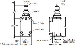
Sealed top-ball plunger With operation indicator
LED
WLD38-LD-N
Neon lamp
WLD38-LE-N
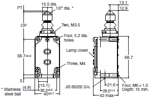
Operating characteristics

Horizontal plunger
WLSD(-55)-N
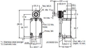
Horizontal plunger With operation indicator
LED
WLSD-(55)LD-N
Neon lamp
WLSD-LE-N
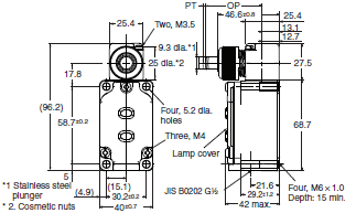
Horizontal-roller plunger
WLSD2(-55)-N
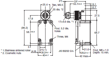
Horizontal-roller plunger With operation indicator
LED
WLSD2-(55)LD-N
Neon lamp
WLSD2-LE-N
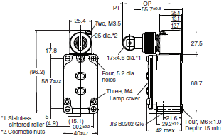
Horizontal-ball plunger
WLSD3-N
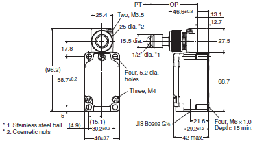
Horizontal-ball plunger With operation indicator
LED
WLSD3-LD-N
Neon lamp
WLSD3-LE-N
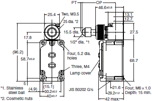
Operating characteristics

Direct-wire connector
Sealed top-roller plunger With operation indicator
LED
WLD28-(55)LDK13-N
WLD28-(55)LDK43-N
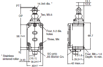
Pre-wired connectors
Sealed top-roller plunger With operation indicator
Threaded (M12)
LED
WLD28-(55)LD-M1J-N
WLD28-(55)LD-M1GJ-N
WLD28-(55)LD-DGJ-N
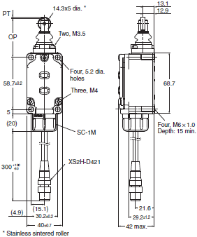
Operating characteristics

Flexible Rod
Screw terminals
Adjustable rod lever (25 to 140 mm)
WLCL(-55)-N
WLCL-2-N
WLCL-2N-N

Adjustable rod lever (25 to 140 mm) With operation indicator
LED
WLCL-(55)LD-N
WLCL-2LD-N
WLCL-2NLD-N
Neon lamp
WLCL-LE-N
WLCL-2LE-N
WLCL-2NLE-N
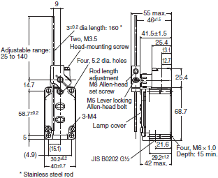
Adjustable rod lever (25 to 140 mm)
WLGL
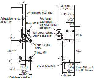
Adjustable Roller Lever (25 to 140 mm) With operation indicator
LED
WLGL-LD
Neon lamp
WLGL-LE
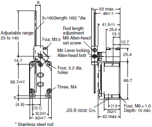
Operating characteristics

Adjustable rod lever (350 to 380 mm)
WLCAL4-N
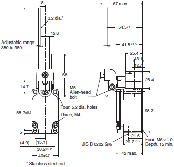
Adjustable Roller Lever (350 to 380 mm) With operation indicator
LED
WLCAL4-LD-N
Neon lamp
WLCAL4-LE-N
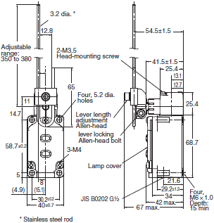
Operating characteristics
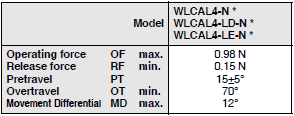
Note: With WLCAL4-N, WLCAL4-LD-N and WLCAL4-LE-N the actuator’s tare is large, so depending on the installation
direction, they may not be properly reset. Always install so that the actuator is facing downwards.
* This is the value when the rod length is 380 mm.
Rod spring lever
WLCAL5-N
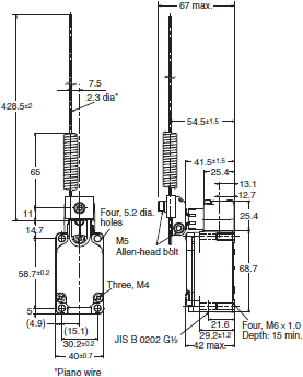
Rod spring lever With operation indicator
LED
WLCAL5-LD-N
Neon lamp
WLCAL5-LE-N
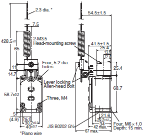

Note: With WLCAL5-N, WLCAL5-LD-N, and WLCAL5-LE-N, the actuator’s tare is large, so depending on the installation
direction, they may not be properly reset. Always install so that the actuator is facing downwards.
* This is the value when the rod length is 380 mm.
Coil spring
WLNJ(-55)-N

Coil spring With operation indicator
LED
WLNJ-(55)LD-N
Neon lamp
WLNJ-LE-N
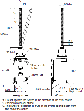
Coil Spring (Multi-wire)
WLNJ-30-N
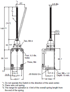
Coil Spring (Multi-wire) With operation indicator
LED
WLNJ-30LD-N
Neon lamp
WLNJ-30LE-N
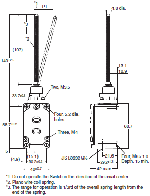
Operating characteristics

Resin rod
WLNJ-2(55)-N
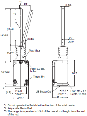
Resin rod With operation indicator
LED
WLNJ-2(55)LD-N
Neon lamp
WLNJ-2LE-N

Steel wire
WLNJ-S2-N

Steel wire With operation indicator
LED
WLNJ-S2LD-N
Neon lamp
WLNJ-S2LE-N
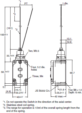
Operating characteristics

Fork Lock Lever
Screw terminals
WLCA32-41-N
WLCA32-42-N
WLCA32-43-N
WLCA32-44-N
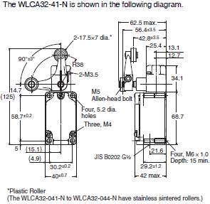
With operation indicator
LED
WLCA32-41LD-N
WLCA32-43LD-N
Neon lamp
WLCA32-41LE-N
WLCA32-42LE-N
WLCA32-43LE-N
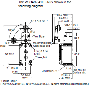
Operating characteristics

Environment-resistant Limit Switches
Roller Lever
Screw terminals
Roller lever R38
Heat-resistant type
WLCA2-TH-N
WLCA2-2TH-N
WLCA2-2NTH-N
Cold-resistant type
WLCA2-TC-N
WLCA2-2TC-N
WLCA2-2NTC-N
Corrosion-resistant type
WLCA2-RP-N
Weather-resistant type
WLCA2-P1-N
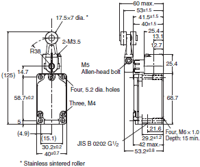
Roller lever R38
Heat-resistant type
WLG2-TH
WLGCA2-TH
Cold-resistant type
WLG2-TC
WLGCA2-TC
Corrosion-resistant type
WLG2-RP
WLGCA2-RP
Weather-resistant type
WLG2-P1

Operating characteristics

Direct-wire cable
Roller lever R38
Coolant-resistant type
WLCA2-RP60-N
WLCA2-2RP60-N
Molded terminal-139
WLCA2-139-N
WLCA2-2139-N
WLCA2-2N139-N
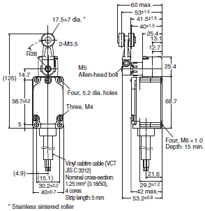
Roller lever R38 With operation indicator
Coolant-resistant specifications
WLCA2-RP60LD2-N
WLCA2-RP60LD3-N
WLCA2-2RP60LD2-N
WLCA2-2RP60LD3-N
Molded terminal -139
WLCA2-139LD2-N
WLCA2-139LD3-N
WLCA2-2139LD2-N
WLCA2-2139LD3-N
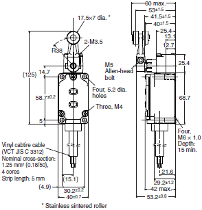
Roller lever R38
Molded terminal-140
WLCA2-140-N
WLCA2-2N140-N
Molded terminal-141
WLCA2-141-N
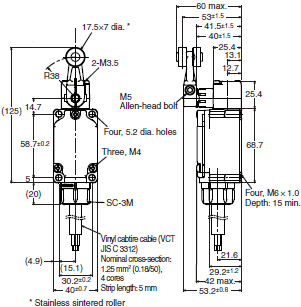
Roller lever R38 With operation indicator
Molded terminal -141
WLCA2-141LD2-N
WLCA2-141LD3-N
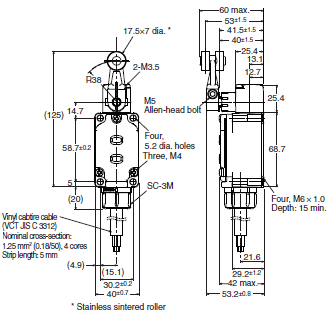
Operating characteristics
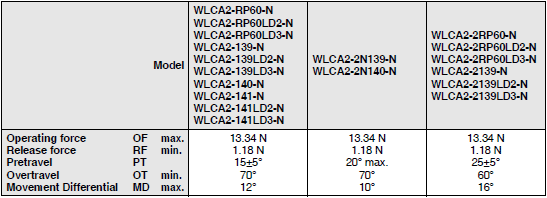
Roller lever R38
Coolant-resistant type
WLG2-RP60
Molded terminal -139
WLG2-139
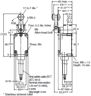
Roller lever R38 With operation indicator
Coolant-resistant specifications
WLG2-RP60LD2
WLG2-RP60LD3
WLGCA2-RP60LD2
WLGCA2-RP60LD3
Molded terminal -139
WLG2-139LD3
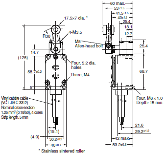
Roller lever R38
Molded terminal -140
WLG2-140
Molded terminal -141
WLG2-141
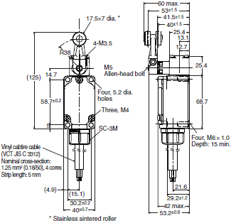
Roller lever R38 With operation indicator
Molded terminal -140
WLG2-140LD2
WLG2-140LD3
Molded terminal -141
WLG2-141LD2
WLG2-141LD3
WLGCA2-141LD3
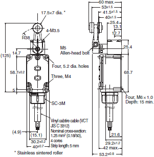
Operating characteristics
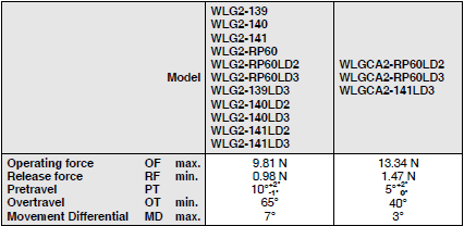
Screw terminals
Adjustable Roller Lever (R25 to 89 mm)
Heat-resistant type
WLCA12-TH-N
WLCA12-2TH-N
WLCA12-2NTH-N
Cold-resistant type
WLCA12-TC-N
WLCA12-2TC-N
WLCA12-2NTC-N
Weather-resistant type
WLCA12-P1-N
Corrosion-resistant type
WLCA12-RP-N
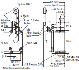
Adjustable Roller Lever (R25 to 89 mm)
Heat-resistant type
WLG12-TH
Cold-resistant type
WLG12-TC
Weather-resistant type
WLG12-P1
Corrosion-resistant type
WLG12-RP
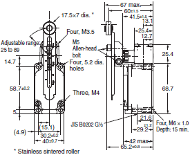
Operating characteristics

Direct-wire cable
Adjustable Roller Lever (R25 to 89 mm)
Coolant-resistant specifications
WLCA12-RP60-N
Molded terminal -139
WLCA12-139-N
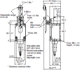
Adjustable Roller Lever (R25 to 89 mm)
Molded terminal -140
WLCA12-140-N
Molded terminal -141
WLCA12-141-N
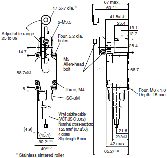
Operating characteristics
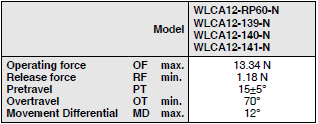
Note: The operating characteristics are measured at the lever length of 38 mm.
Plunger Actuators
Screw terminals
Sealed top-roller plunger
Heat-resistant specifications
WLD28-TH-N
Cold-resistant specifications
WLD28-TC-N
Corrosion-resistant specifications
WLD28-RP-N
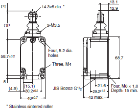
Top-roller plunger
Heat-resistant specifications
WLD2-TH-N
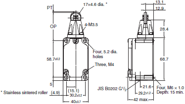
Horizontal plunger
Heat-resistant specifications
WLSD-TH-N
Cold-resistant specifications
WLSD-TC-N
Corrosion-resistant specifications
WLSD-RP-N
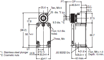
Horizontal-roller plunger
Heat-resistant specifications
WLSD2-TH-N
Cold-resistant specifications
WLSD2-TC-N
Corrosion-resistant specifications
WLSD2-RP-N
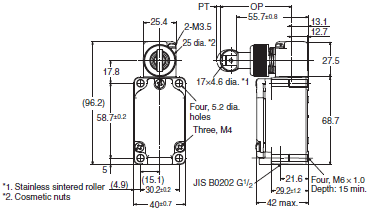
Operating characteristics

Direct-wire cable
Sealed top-roller plunger
Coolant-resistant specifications
WLD28-RP60-N
Molded terminal -139
WLD28-139-N
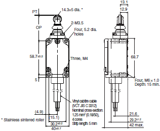
Sealed top-roller plunger
Molded terminal -140
WLD28-140-N
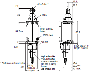
Top-roller plunger
Coolant-resistant specifications
WLD2-RP60-N
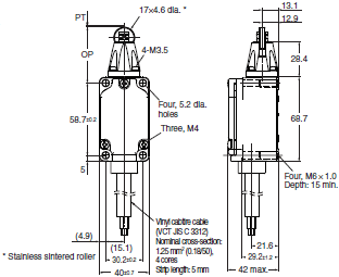
Horizontal plunger
Molded terminal -139
WLSD-139-N
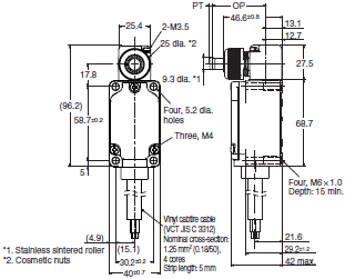
Horizontal-roller plunger
Coolant-resistant specifications
WLSD2-RP60-N
Molded terminal -139
WLSD2-139-N
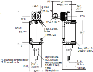
Horizontal-roller plunger
Molded terminal -140
WLSD2-140-N
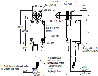
Operating characteristics

Flexible Rod
Screw terminals
Coil spring
Heat-resistant specifications
WLNJ-TH-N
Cold-resistant specifications
WLNJ-TC-N
Corrosion-resistant
specifications
WLNJ-RP-N
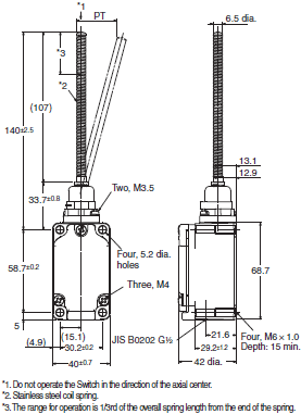
Resin rod
Corrosion-resistant specifications
WLNJ-2RP-N
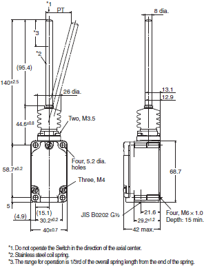
Operating characteristics

Direct-wire cable
Coil spring
Coolant-resistant specifications
WLNJ-RP60-N
Molded terminal -139
WLNJ-139-N
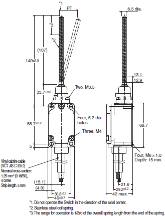
Coil spring
Molded terminal -140
WLNJ-140-N
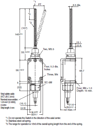
Resin rod
Coolant-resistant specifications
WLNJ-2RP60-N
Molded terminal -139
WLNJ-2139-N
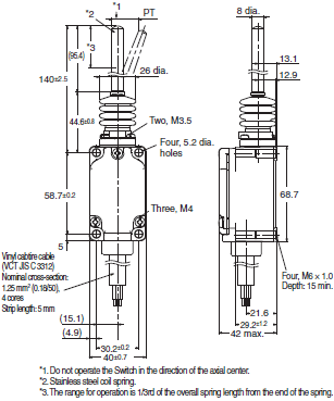
Resin rod
Molded terminal – 140
WLNJ-2140-N
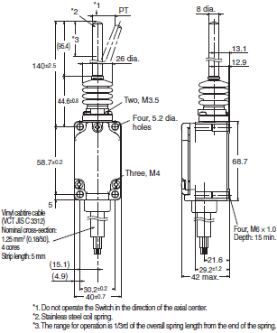
Operating characteristics
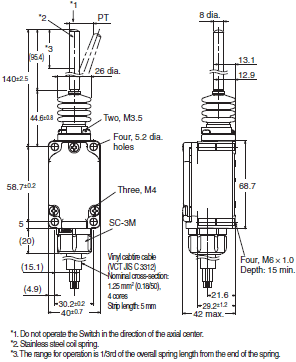
Spatter-prevention Switches
Roller Lever
Roller lever R38
Allen-head lever
With operation indicator (LED)
WLCA2-LDS-N
With operation indicator (neon lamp)
WLCA2-LES-N

Roller lever R38
Allen-head lever
With operation indicator (LED)
WLG2-LDS
WLGCA2-LDS
With operation indicator (neon lamp)
WLG2-LES
WLGCA2-LES
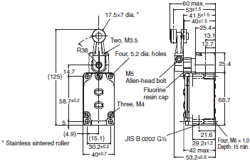
Roller lever R38
Double nut lever
With operation indicator (LED)
WLCA2-LDAS-N
With operation indicator (neon lamp)
WLCA2-LEAS-N
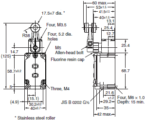
Roller lever R38
Double nut lever
With operation indicator (LED)
WLG2-LDAS
With operation indicator (neon lamp)
WLG2-LEAS
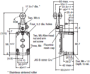
Operating characteristics
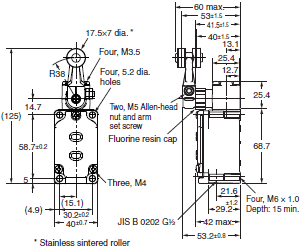
Pre-wired connector (threaded)
Roller lever R38
Allen-head lever
With operation indicator (LED)
WLCA2-LDS-M1J-1-N
WLCA2-LDS-DGJS-N

Roller lever R38
Allen-head lever
Threaded (M12)
With operation indicator (LED)
WLG2-LDS-DGJS03
WLG2-LDS-DK1EJ03
WLG2-55LDS-M1J-1
WLG2-55LDS-M1GJ-1
WLG2-55LDS-DGJS03
WLG2-LDS-M1J-1
WLG2-LDS-M1GJ-1
WLGCA2-LDS-M1J-1
WLGCA2-LDS-M1GJ-1
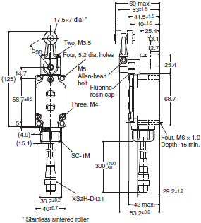
Pre-wired connector type (Smartclick)
Roller lever R38
Allen-head lever
With operation indicator (LED)
WLCA2-LDS-DTGJS-N
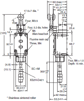
Roller lever R38
Allen-head lever
Smartclick
With operation indicator (LED)
WLG2-LDS-DTGJS03
WLG2-55LDS-M1TGJ
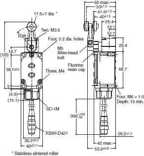
Operating characteristics
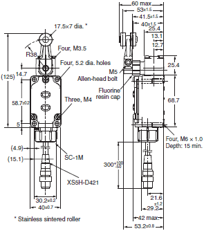
Sealed top-roller plunger
With operation indicator
LED
WLD28-LDS-N
Neon lamp
WLD28-LES-N
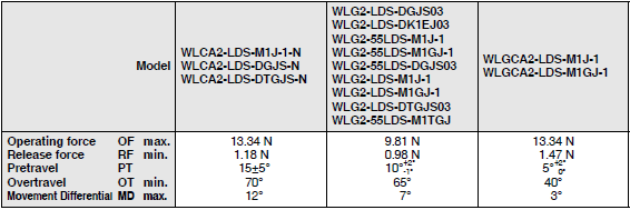
Sealed top-roller plunger
Threaded (M12)
WLD28-LDS-M1J-1-N
WLD28-LDS-M1GJ-1-N
WLD28-LDS-DGJS-N
Smartclick
WLD28-LDS-DTGJS-N
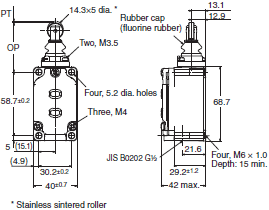
Operating characteristics
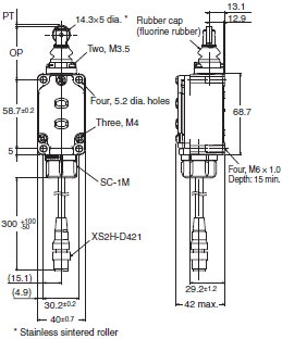
Long-life Switches
Roller Lever
Screw terminals
Roller lever R38
With operation indicator (LED)
WLMCA2-LD-N
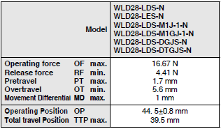
Roller lever R38
With operation indicator (LED)
WLMG2-LD
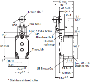
Roller lever R38
With operation indicator (LED)
WLMGCA2-LD
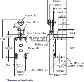
Operating characteristics
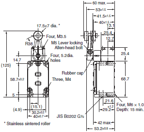
Direct-wire connector
Roller lever R38
With operation indicator (LED)
WLMCA2-LDK13A-N
WLMCA2-LDK43A-N
WLMCA2-LDK13-N
WLMCA2-LDK43-N

Roller lever R38
With operation indicator (LED)
WLMG2-LDK13A
WLMG2-LDK43A
WLMG2-LDK13
WLMG2-LDK43
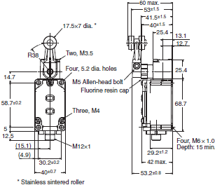
Roller lever R38
With operation indicator (LED)
WLMGCA2-LDK13A
WLMGCA2-LDK43A
WLMGCA2-LDK13
WLMGCA2-LDK43
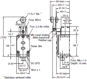
Operating characteristics
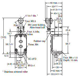
Pre-wired connectors
Roller lever R38
With operation indicator (LED)
Threaded (M12)
WLMCA2-LD-M1J-N
WLMCA2-LD-AGJ-N
WLMCA2-LD-DGJ-N
Smartclick
WLMCA2-LD-DTGJ-N

Roller lever R38
With operation indicator (LED)
Threaded (M12)
WLMG2-LD-M1J
WLMG2-LD-DTGJ03
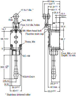
Roller lever R38
With operation indicator (LED)
Threaded (M12)
WLMGCA2-LD-M1J
Smartclick
WLMGCA2-LD-DTGJ03
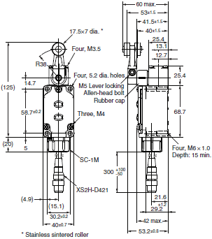
Operating characteristics
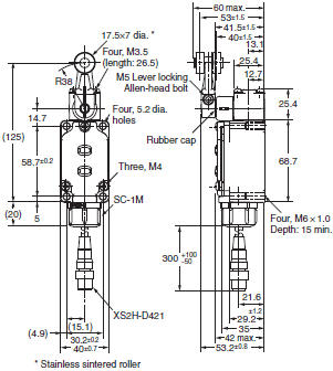
Common Accessories (Sold Separately)
Operating characteristics
Sensor I/O connectors
XS2F-A421-[][]0-F
XS2F-D421-[]D0
XS2F-D421-[][]0-F

XS5F-D421-[]80-F

Terminal Plate
WL-N TERMINAL PLATE

Side mounting plate
WLN-P001
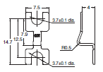
SC-2F

SC-2FAD

SC-4F4AD

SC-4F4D

Note: Figures in parentheses are connector pin numbers.
Actuator
WL-1A100
Standard Lever

WL-1A115
Resin Roller
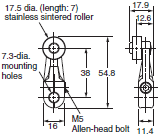
WL-1A400
Bearing Roller
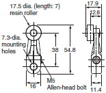
WL-1A118
Nylon Roller: Roller Width: 30 mm
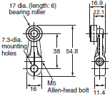
WL-1A105
Double Nuts
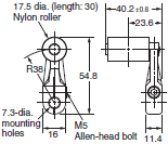
WL-1A103S
Spatter Prevention
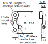
WL-105S
Spatter Prevention
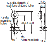
WL-1A200
Lever Length: 50
Roller Width: 15
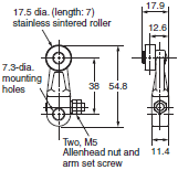
WL-1A300
Lever Length: 63
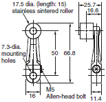
WL-2A100
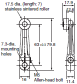
WL-2A111
Resin Roller
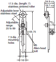
WL-2A107
Double Nuts
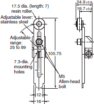
WL-2A108
Resin Roller
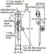
WL-2A122
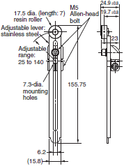
WL-2A106
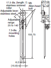
WL-2A130
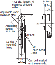
WL-2A104
0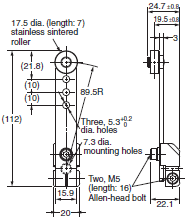
WL-2A110
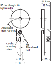
WL-2A105
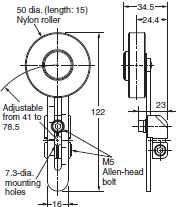
WL-1A106
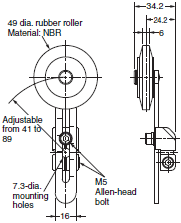
WL-1A110
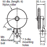
WL-4A100
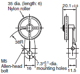
WL-4A201
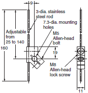
WL-3A100
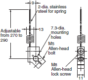 WL-3A106
Double Nut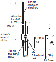
WL-3A108
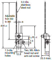
WL-3A200
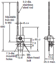
WL-3A203
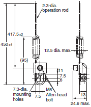
WL-4A112
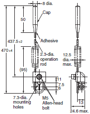
WL-2A129
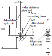
WL-5A101

WL-5A103
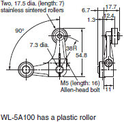
WL-5A105
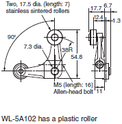
Note: When using the adjustable roller (rod) lever, make sure that the lever is facing downwards. Use caution, as
telegraphing (the Switch turns ON and OFF repeatedly due to inertia) may occur.
Connector (Conduit size: JIS B0202G1/2)
SC-1M
SC-2M
SC-3M
SC-4M
SC-5M
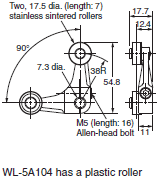
SC-21
SC-22
SC-23
SC-24
SC-25

SC-6

SC-P2

* mark dimensional table

* mark dimensional table
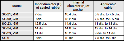
Features | Limit Switches – WL-N / WL
A type with operation indicators for easily confirming operation is available
- Environment resistant models for harsh environments, spatter resistant models for welding processes, and long-life models for high-frequency us
- Available LED operation indicators
- Available pre-wired
- Available with 2 m and 5 m I/O cables with M12 connectors
- IP67 rated
Properties | Limit Switches – WL-N / WL
| Limit Switches | WL-N / WL | |
|---|---|---|
| Switching standard loads | 10A | 250 VAC |
| 1A | 30 VDC | |
| Life expectancy | 30,000,000 operations min. | |
| dimensions | 30.2 x 58.7 mm | |
| rated | IP67 | |


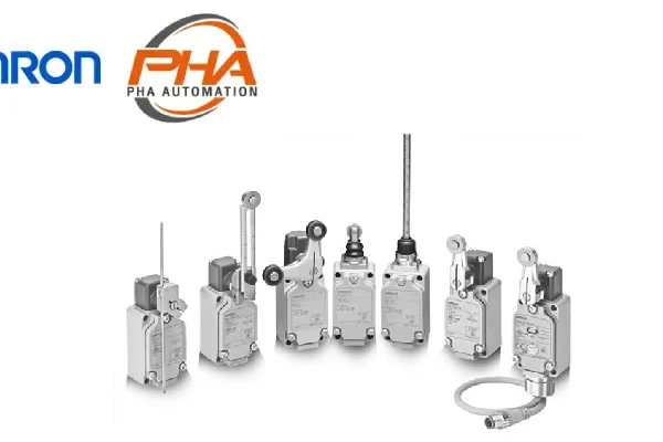
![OMRON Limit Switches - ZC-[]55](https://www.pha-auto.co.th/wp-content/uploads/2023/12/ZC-55-100x100.webp)
![OMRON Limit Switches - ZC-[]55](https://www.pha-auto.co.th/wp-content/uploads/2023/12/ZC-55.webp)

