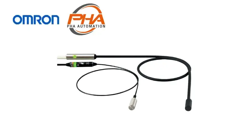
OMRON Proximity Sensor - E2EC-M-Q

OMRON Proximity Sensor Separate Amplifier – E2EC-M-Q
Model Numbers | Proximity Sensor Separate Amplifier – E2EC-M-Q
Sensors
| Appearance | Sensing distance | Output configuration | Model | |
|---|---|---|---|---|
| Operation mode: NO | ||||
Shielded When mounting to an iron surface |
8 dia. | 2 mm | DC 3-wire PNP | E2EC-MC2B1 2M |
| DC 2-wire (polarity) | E2EC-MC2D1 2M | |||
| DC 2-wire (no polarity) (3)-(4) pin arrangement |
E2EC-QC2D1-M1GJ-T 0.3M | |||
Accessories (Order Separately)
Sensor I/O Connector
Models with Pre-wired Connectors: A Connector is not provided with the Sensor. Be sure to order a Connector separately.
| Appearance | Cable length | Sensor I/O Connector model | Applicable Proximity Sensors | |
|---|---|---|---|---|
| Straight |  |
2 m | XS2F-D421-DD0 | E2EC-QC2D1-M1GJ-T |
| 5 m | XS2F-D421-GD0 | |||
| L-shape |  |
2 m | XS2F-D422-DD0 | |
| 5 m | XS2F-D422-GD0 | |||
Note: The Sensor I/O Connector models in the previous table are for standard cables. Be sure to use a heat-resistant
cable (XS2F-D42[]-[]80F) when using the Sensor in environments susceptible to spatter.
Specifications | Proximity Sensor Separate Amplifier – E2EC-M-Q
| Type | DC 3-Wire PNP Models | DC 2-Wire Models | DC 2-Wire Models (no polarity) (spatter-resistant type) |
||
|---|---|---|---|---|---|
| Model | E2EC-MC2B1 | E2EC-MC2D1 | E2EC-QC2D1-M1GJ-T | ||
| Size | 8 dia. (Sensing Head) | ||||
| Shielding | Shielded | ||||
| Sensing distance | 2 mm ± 15% | 2 mm ± 10% | |||
| Set distance | 0 to 1.2 mm | 0 to 1.4 mm | |||
| Differential travel | 15% max. of sensing distance | ||||
| Detectable object | Ferrous metals (The sensing distance will decreases with non-ferrous metal. Refer to Engineering Data (Reference Value) on Data Sheet.) | ||||
| Standard sensing object | Iron, 8 × 8 × 1 mm | ||||
| Response frequency | 100 Hz | ||||
| Power supply voltage (operating voltage range) |
12 to 24 VDC, ripple (p-p): 10% max. (10 to 30 VDC) | ||||
| Current consumption | 10 mA max. | — | |||
| Leakage current | — | 0.8 mA max. | |||
| Control output |
Load current | 100 mA max. | 3 to 50 mA | ||
| Residual voltage | 2 V max. (Load current: 100 mA, Cable length: 2 m) |
3 V max. (Load current: 50 mA, Cable length: 2 m) |
5 V max. (Load current: 50 mA, Cable length: 2 m) |
||
| Indicators | Operation indicator (yellow) | Operation indicator (red), Setting indicator (green) | |||
| Operation mode (with sensing object approaching) |
NO (normally open) Refer to the timing charts under I/O Circuit Diagrams on Data Sheet for details. |
||||
| Protection circuits | Power supply reverse polarity protection, Surge suppressor, Load short-circuit protection, Reversed output polarity protection |
Surge suppressor, Load short-circuit protection | |||
| Ambient temperature range | Operating and storage: – 25 to 70 ° C (with no icing or condensation) | ||||
| Ambient humidity range | Operating and storage: 35% to 95% (with no condensation) | ||||
| Temperature influence | ± 20% max. of sensing distance at 23 ° C in the temperature range of – 25 to 70 ° C | ||||
| Voltage influence | ± 5% max. of sensing distance at rated voltage in the rated voltage ± 15% range |
± 1% max. of sensing distance at the rated voltage range in the voltage range of ± 15% |
|||
| Insulation resistance | 50 MΩ min. (at 500 VDC) between current-carrying parts and case | ||||
| Dielectric strength | 1,000 VAC for 1 min between current carrying-parts and case | ||||
| Vibration resistance | Destruction: 10 to 55 Hz, 1.5-mm double amplitude for 2 hours each in X, Y, and Z directions | ||||
| Shock resistance | Destruction: 1,000 m/s2 10 times each in X, Y, Z directions | ||||
| Degree of protection | IEC IP67, In-house standards: oil-resistant (For Sensor Head only) | ||||
| Connection method | Pre-wired Connector Models (Standard cable length: 2 m) | Connector Models (Standard cable length: 0.3 m) |
|||
| Weight (packed state) | Approx. 65 g | Approx. 95 g | |||
| Materials | Sensor Head |
Case | Stainless steel (SUS303) | Stainless steel (SUS303) Fluororesin coated |
|
| Sensing surface (thickness) |
Stainless steel (SUS303) (0.2 mm) | Stainless steel (SUS303) Fluororesin coated (0.2 mm) |
|||
| Cable | Polyester elastomer (TPEE) (Shielded) | Fluoro-rubber (Shielded) | |||
| Cable Amplifier |
Case | ABS resin | Stainless steel (SUS303) | ||
| Cable | Polyvinyl chloride (PVC) | Fluorocarbon cable (flame-resistant) | |||
| Accessories | Amplifier Mounting Bracket, instruction manual | ||||
Note: Time is required for the sensing distance to stabilize after the power supply is turned ON. Confirm operation
sufficiently in the actual operating environment and use the Sensor within the set distance to obtain a sufficient sensing distance.
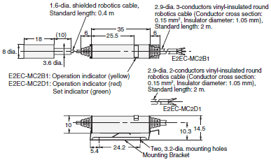
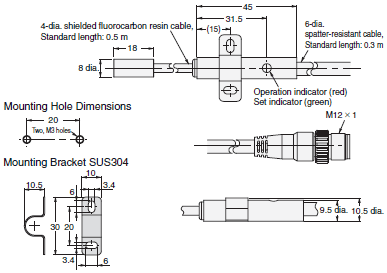
Dimensions | Proximity Sensor Separate Amplifier – E2EC-M-Q
Tolerance class IT16 applies to dimensions in this data sheet unless otherwise specified.
Sensors
E2EC-MC2B1, E2EC-MC2D1

E2EC-QC2D1-M1GJ-T

Sensing Head Mounting Hole Dimensions

คุณสมบัติ | Proximity Sensor Separate Amplifier – E2EC-M-Q
- เพิ่มความทนทานด้วยหัวตรวจสแตนเลส
- เป็นรุ่นที่ทนทานต่อสะเก็ดไฟที่ดีขึ้นซึ่งเหมาะสมสำหรับงานเชื่อม
คุณสมบัติ | Proximity Sensor Separate Amplifier – E2EC-M-Q
| Proximity Sensor Separate Amplifier | E2EC-M-Q | |
|---|---|---|
| หัวเซนเซอร์ | ระยะตรวจจับ | 0 – 1.5, 0 – 2, 0 – 3 mm |
| การตรวจจับ | วัตถุโลหะไม่ใช่เหล็ก | |
| ระดับการป้องกัน | IP67 | |
| วัสดุ | สแตนเลส, สังกะสีหล่อ | |
| แอมพลิฟายเออร์ | แรงดันไฟฟ้า | 10 – 30 VDC |
| การใช้พลังงาน | 1,080 มิลลิวัตต์ | |
| ระดับการป้องกัน | IP50 | |
| วัสดุตัวเรือน | PBT | |
ติดต่อแผนก Automation & Robots


