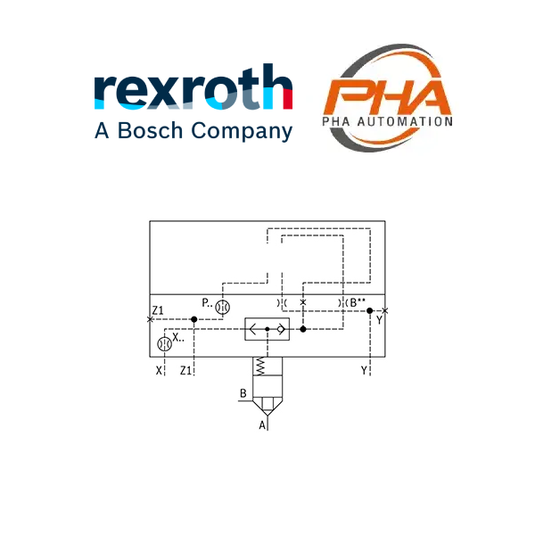
CARTRIDGE VALVE รุ่น LFA..KWB
2-way cartridge valves, directional functions รุ่น LFA..KWB (control cover)

Cartridge Valves รุ่น LFA..KWB
รายละเอียด Cartridge Valves รุ่น LFA..KWB
- Size 16 … 100
- Component series 6X, 7X
- Maximum operating pressure 420 bar
- Maximum flow 25000 l/min
Features
- 2 area ratios
-
4 different springs
Type code
| 01 | 02 | 03 | 04 | 05 | 06 | 07 | 08 | ||
|---|---|---|---|---|---|---|---|---|---|
| LFA | KWB | – | / |
| Type | |||
|---|---|---|---|
| 01 | Control cover LFA | LFA | |
| Size | |||
| 02 | NG 16 | 16 | |
| NG 25 | 25 | ||
| NG 32 | 32 | ||
| NG 40 | 40 | ||
| NG 50 | 50 | ||
| NG 63 | 63 | ||
| NG 80 | 80 | ||
| NG 100 | 100 | ||
| Version | |||
| 03 | Control cover version “KWB” | For set-up of a directional spool or seat valve with integrated shuttle valve as check valve circuit | KWB |
| Component series | |||
| 04 | Component series 70 to 79 (70 to 79: unchanged installation and connection dimensions) 1) | 7X | |
| Component series 60 to 69 (60 to 69: unchanged installation and connection dimensions) 2) | 6X | ||
| Nozzle fitting | |||
| 05 | Orifice in channel B 3) | B.. | |
| 06 | Orifice in channel P 3) | P.. | |
| 07 | Orifice in channel T 3) | T.. | |
| 08 | Orifice in channel X 3) | X.. | |
- Component series 7X for sizes 16…63
- Component series 6X for sizes 80 and 100.
- This orifice is designed as screw-type orifice. If an orifice is to be installed, the respective code letter with the orifice Ø in 1/10 mm has to be entered in the type designation.
- Example: X12 = Orifice with Ø1.2 mm in channel X.
| Size | Orifice in the channel | |||
|---|---|---|---|---|
| A | P | T | X | |
| 16 | B 3) | P15 | – | Z12 |
| 25 | B 3) | P15 | – | Z12 |
| 32 | B 3) | P20 | – | Z12 |
| 40 | B 3) | P20 | – | Z12 |
| 50 | B 3) | P20 | – | Z12 |
| 63 | B 3) | P25 | T 3) | X 3) |
| 80 | B 3) | P25 | T 3) | X20 |
| 100 | B 3) | P25 | T 3) | X20 |
- This orifice is designed as screw-type orifice. If an orifice is to be installed, the respective code letter with the orifice Ø in 1/10 mm has to be entered in the type designation.
- Example: X12 = Orifice with Ø1.2 mm in channel X.
| Orifice symbol | Symbol in ordering code | ||
|---|---|---|---|
| A** |  |
A** | This orifice is designed as screw-type orifice. If an orifice is to be installed, the respective code letter with the orifice Ø in 1/10 mm has to be entered in the type designation. Example: A12 = Orifice with Ø1.2 mm in channel A. |
| Ø1,2 |  |
This orifice is designed as bore. No specifications are made in the type designation. (Orifice Ø in mm) | |
| Z12 |  |
This orifice is designed as screw-type orifice. This is a standard orifice. No specifications are made in the type designation. (Orifice Ø in 1/10 mm) | |
| Model | Code |
|---|---|
| LFA 16 KWB-7X/ | R900912651 |
| LFA 16 KWB-7X/B08 | R900943142 |
| LFA 25 KWB-7X/ | R900912692 |
| LFA 25 KWB-7X/B10 | R901053278 |
| LFA 25 KWB-7X/B12 | R900730489 |
| LFA 25 KWB-7X/P10 | R900976053 |
| LFA 32 KWB-7X/ | R900912726 |
| LFA 32 KWB-7X/B10/12 | R900737795 |
| LFA 32 KWB-7X/B12P08 | R901272747 |
| LFA 32 KWB-7X/B25 | R901142756 |
| LFA 40 KWB-7X/ | R900938136 |
| LFA 40 KWB-7X//12 | R901042211 |
| LFA 40 KWB-7X/B15V/12 | R901174978 |
| LFA 40 KWB-7X/P25X25 | R901252014 |
| LFA 50 KWB-7X/ | R900938211 |
| LFA 50 KWB-7X/B30 | R901273385 |
| LFA 63 KWB-7X/ | R900938256 |


