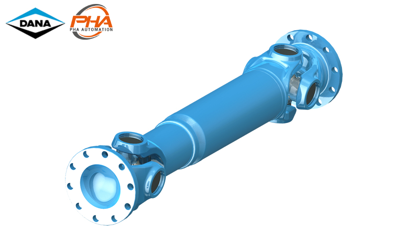
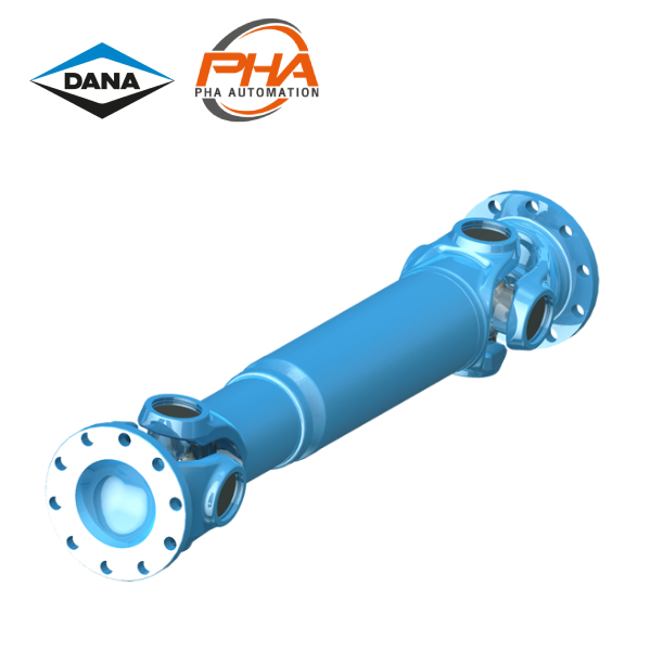
DANA Closed bearing eye - series 687/688

DANA Closed bearing eye – series 687/688
Feature | DANA Closed bearing eye 687/688
- Torque Range TCS : From 2,4 to 35 kNm
- Flange diameter : From 100 mm to 225 mm
- Field of application
- Railway vehicles
- Rolling mill plants
- Marine drives
- General machinery construction plants
Specifications | DANA Closed bearing eye 687/688
ตารางสเปค 1 (Specification 1)
Shaft Specification | DANA Closed bearing eye 687/688
- 0.02 with length compensation, tubular design
- 0.03 without length compensation, tubular design
- 9.01, 9.03 with length compensation, short design
- 9.04 without length compensation, double flange shaft design
| Shaft size | 687/688.15 | 687/688.20 | 687/688.25 | 687/688.30 | 687/688.35 | 687/688.40 | ||||||
|---|---|---|---|---|---|---|---|---|---|---|---|---|
| TCS | kNm | 2.4 | 3.5 | 5 | 6.5 | 10 | 14 | |||||
| TDW | kNm | 0.7 | 1.0 | 1.6 | 1.9 | 2.9 | 4.4 | |||||
| LC | – | 1.79 x 10⁻⁴ | 5.39 x 10⁻⁴ | 1.79 x 10⁻³ | 2.59 x 10⁻³ | 0.0128 | 0.0422 | |||||
| β | <) ° | 25 | 25 | 25 | 25 | 25 | 25 | 44 | 25 | 44 | ||
| A | mm | 100 | 120 | 120 | 120 | 150 | 150 | 180 | 150 | 150 | 180 | 180 |
| K | mm | 90 | 98 | 113 | 127 | 127 | 144 | 144 | 160 | 160 | 160 | 160 |
| B ±0.1mm | mm | 84 | 101.5 | 101.5 | 101.5 | 130 | 130 | 155.5 | 130 | 130 | 155.5 | 155.5 |
| C H7 | mm | 57 | 75 | 75 | 75 | 90 | 90 | 110 | 90 | 90 | 110 | 110 |
| F1) | mm | 2.5 | 2.5 | 2.5 | 2.5 | 3 | 3 | 3 | 3 | 3 | 3 | 3 |
| G | mm | 7 | 8 | 8 | 8 | 10 | 10 | 12 | 10 | 10 | 12 | 12 |
| H +0.2mm | mm | 8.25 | 10.25 | 10.25 | 10.25 | 12.25 | 12.1 | 14.1 | 12.1 | 12.1 | 14.1 | 14.1 |
| I2) | – | 6 | 8 | 8 | 8 | 8 | 8 | 8 | 8 | 8 | 8 | 8 |
| M | mm | 48 | 54 | 70 | 72 | 78 | 95 | 90 | 102 | 102 | 102 | 102 |
| S | mm | 63.5 x 2.4 | 76.2 x 2.4 | 89 x 2.4 | 90 x 3 | 90 x 3 | 100 x 3 | 100 x 3 | 120 x 3 | 100 x 4.5 | 120 x 3 | 100 x 4.5 |
| W DIN 5480 | mm | 36 x 1.5 | 40 x 1.5 | 45 x 1.5 | 48 x 1.5 | 48 x 1.5 | 54 x 1.5 | 54 x 1.5 | 62 x 1.75 | |||
- Tcs : Functional limit torque* : If the permissible function limit torque TCS is to ne fully uitilized, the flange connection (e.g., witth dowel pins) must be reinforced. Yieid torque 30% over TCS
- TDW : Reversing fatigue torque*
- LC : Bearing capacity factor* : See specifications of driveshafts.
- β : Maximum deflection angle per joint
- Tubular shaft with welded-on balancing plates have lower fatigues TDW
- 1 Effective spigot depth
- 2 Number of flange holes
Specification | DANA Closed bearing eye 687/688
| Design | Shaft size | 687/688.15 | 687/688.20 | 687/688.25 | 687/688.30 | 687/688.35 | 687/688.40 | ||||||
|---|---|---|---|---|---|---|---|---|---|---|---|---|---|
| 0.02 | Lz min | mm | 346 | 379 | 458 | 492 | 504 | 582 | 572 | 586 | 693 | 586 | 693 |
| La | mm | 60 | 70 | 100 | 110 | 110 | 110 | 1100 | 110 | 180 | 110 | 180 | |
| G | kg | 5.7 | 8.4 | 12.0 | 13 | 14.2 | 24.0 | 25.6 | 28.7 | 30.3 | 29.4 | 30.9 | |
| GR | kg | 3.62 | 4.37 | 5.13 | 6.44 | 6.44 | 7.18 | 7.18 | 8.66 | 10.6 | 8.66 | 10.6 | |
| Jm | kgm2 | 0.0043 | 0.0089 | 0.0144 | 0.0245 | 0.0245 | 0.043 | – | 0.0676 | 0.0706 | 0.0776 | 0.0806 | |
| JmR | kgm2 | 0.0034 | 0.0059 | 0.0096 | 0.0122 | 0.0122 | 0.169 | 0.0169 | 0.0296 | 0.242 | 0.296 | 0.0242 | |
| C | Nm/rad. | 0.26 x 10⁵ | 0.86 x 10⁵ | 1.44 x 10⁵ | 1.74 x 10⁵ | 1.74 x 10⁵ | 1.81 x 10⁵ | – | 2.17 x 10⁵ | 1.61 x 10⁵ | 2.17 x 10⁵ | 1.61 x 10⁵ | |
| CR | Nm/rad | 0.34 x 10⁵ | 0.60 x 10⁵ | 0.98 x 10⁵ | 1.25 x 10⁵ | 1.25 x 10⁵ | 1.72 x 10⁵ | 1.72 x 10⁵ | 3.02 x 10⁵ | 2.47 x 10⁵ | 3.02 x 10⁵ | 2.47 x 10⁵ | |
| 0.03 | Lf min | mm | 221 | 239 | 282 | 310 | 322 | 379 | 369 | 423 | 449 | 423 | 449 |
| G | kg | 4.1 | 5.8 | 8.6 | 8.6 | 9.8 | 18.0 | 19.6 | 22.8 | 21.0 | 23.4 | 21.6 | |
| Jm | kgm2 | 0.0038 | 0.0085 | 0.0129 | 0.0238 | 0.0238 | 0.04 | – | 0.066 | 0.0628 | 0.076 | 0.0728 | |
| C | Nm/rad | 0.44 x 10⁵ | 0.8 x 10⁵ | 1.44 x 10⁵ | 1.74 x 10⁵ | 1.74 x 10⁵ | 1.81 x 10⁵ | – | 3.35 x 10⁵ | 2.78 x 10⁵ | 3.35 x 10⁵ | 2.78 x 10⁵ | |
| 9.01 | Lz min | mm | 296 | 322 | 361 | 379 | 391 | 510 | 500 | 505 | 525 | 505 | 525 |
| La min | mm | 38 | 41 | 36 | 36 | 36 | 70 | 70 | 70 | 60 | 70 | 60 | |
| Lz max | mm | 348 | 381 | 425 | 453 | 465 | 550 | 540 | 545 | 645 | 545 | 645 | |
| La max | mm | 90 | 100 | 100 | 110 | 110 | 110 | 110 | 110 | 180 | 110 | 180 | |
| 9.03 | Lz min | mm | 245 | 274 | 313 | 331 | 343 | 419 | 409 | 441 | – | 441 | – |
| La min | mm | 25 | 27 | 28 | 29 | 29 | 45 | 45 | 45 | – | 45 | – | |
| Lz max | mm | 280 | 317 | 355 | 397 | 409 | 484 | 474 | 506 | – | 506 | – | |
| La max | mm | 60 | 70 | 70 | 95 | 95 | 110 | 110 | 110 | – | 110 | – | |
| 9.04 | Lf min | mm | 192 | 216 | 280 | 288 | 312 | 380 | 360 | 408 | 408 | 408 | 408 |
- Lz min = Shortest possible compressed length
- La = Length compensation
- Lf min = Shortest fixed length
- Lz + La = Maximum operating length
- G = Weight of shaft
- GR = Weight per 1.000 mm tube
- Jm = Moment of inertia
- JmR = Moment of inertia per 1.000 mm tube
- C = Torsional stiffness of shaft without tube
- CR = Torsional stiffness per 1.000 mm tube
- * Larger length conpensation available on request
ตารางสเปค 2 (Specification 2)
Shaft Specification | DANA Closed bearing eye 687/688
- 0.02 with length compensation, tubular design
- 0.03 without length compensation, tubular design
- 9.01, 9.03 with length compensation, short design
- 9.04 without length compensation, double flange shaft design
| Shaft size | 687/688.45 | 687/688.55 | 687/688.65 | ||||||
|---|---|---|---|---|---|---|---|---|---|
| TCS | kNm | 17 | 25 | 35 | |||||
| TDW | kNm | 5.1 | 7.3 | 11 | |||||
| LC | – | 0.13 | 0.29 | 0.82 | |||||
| β | <) ° | 25 | 35 | 25 | 25 | 35 | 25 | 25 | 25 |
| A | mm | 180 | 180 | 225 | 180 | 180 | 225 | 180 | 225 |
| K | mm | 174 | 174 | 174 | 178 | 178 | 178 | 204 | 204 |
| B ±0.1mm | mm | 155.5 | 155.5 | 196 | 155.5 | 155.5 | 196 | 155.5 | 196 |
| C H7 | mm | 110 | 110 | 140 | 110 | 110 | 140 | 110 | 140 |
| F1) | mm | 3 | 3 | 5 | 3 | 3 | 5 | 3 | 5 |
| G | mm | 12 | 12 | 15 | 14 | 14 | 15 | 15 | 15 |
| H +0.2mm | mm | 14.1 | 14.1 | 16.1 | 16.1 | 16.1 | 16.1 | 16.1 | 16.1 |
| I2) | – | 8 | 8 | 8 | 10 | 10 | 8 | 10 | 8 |
| M | mm | 95 | 95 | 90 | 115 | 115 | 95 | 110 | 110 |
| S | mm | 120 x 4 | 110 x 5 | 120 x 4 | 120 x 6 | 120 x 6 | 120 x 6 | 142 x 6 | 142 x 6 |
| W DIN 5480 | mm | 68 x 1.75 | 78 x 2 | 88 x 2.5 | |||||
- Tcs : Functional limit torque* : If the permissible function limit torque TCS is to ne fully uitilized, the flange connection (e.g., witth dowel pins) must be reinforced. Yieid torque 30% over TCS
- TDW : Reversing fatigue torque*
- LC : Bearing capacity factor* : See specifications of driveshafts.
- β : Maximum deflection angle per joint
- Tubular shaft with welded-on balancing plates have lower fatigues TDW
- 1 Effective spigot depth
- 2 Number of flange holes
Specification | DANA Closed bearing eye 687/688
| Design | Shaft size | 687/688.45 | 687/688.55 | 687/688.65 | ||||||
|---|---|---|---|---|---|---|---|---|---|---|
| 0.02 | Lz min | mm | 595 | 703 | 585 | 662 | 681 | 622 | 686 | 686 |
| La | mm | 110 | 180 | 110 | 110 | 110 | 110 | 110 | 110 | |
| G | kg | 35.7 | 38.4 | 37.7 | 44.0 | 49.2 | 47.0 | 60.6 | 64.6 | |
| GR | kg | 11.44 | 12.95 | 11.44 | 16.87 | 16.87 | 16.87 | 20.12 | 20.12 | |
| Jm | kgm2 | 0.1002 | 0.1242 | 0.1342 | 0.131 | – | 0.151 | 0.2224 | 0.2614 | |
| JmR | kgm2 | 0.0385 | 0.358 | 0.0385 | 0.055 | – | 0.055 | 0.0932 | 0.0932 | |
| C | Nm/rad. | 3.10 x 10⁵ | 2.18 x 10⁵ | 3.10 x 10⁵ | 4.05 x 10⁵ | – | 4.05 x 10⁵ | 5.63 x 10⁵ | 5.63 x 10⁵ | |
| CR | Nm/rad | 3.93 x 10⁵ | 3.65 x 10⁵ | 3.93 x 10⁵ | 5.60 x 10⁵ | 5.60 x 10⁵ | 5.60 x 10⁵ | 9.50 x 10⁵ | 9.50 x 10⁵ | |
| 0.03 | Lf min | mm | 425 | 425 | 415 | 475 | 495 | 435 | 491 | 491 |
| G | kg | 28.0 | 27.8 | 30 | 33.1 | – | 36.1 | 47.3 | 51.3 | |
| Jm | kgm2 | 0.0954 | 0.0976 | 0.1294 | 0.1176 | – | 0.1376 | 0.2032 | 0.2422 | |
| C | Nm/rad | 4.82 x 10⁵ | 3.71 x 10⁵ | 4.82 x 10⁵ | 5.39 x 10⁵ | – | 5.39 x 10⁵ | 7.17 x 10⁵ | 7.17 x 10⁵ | |
| 9.01 | Lz min | mm | 517 | 538 | 507 | 587 | 606 | 547 | 601 | 601 |
| La min | mm | 70 | 60 | 70 | 70 | 70 | 70 | 70 | 70 | |
| Lz max | mm | 557 | 658 | 547 | 617 | 636 | 577 | 641 | 641 | |
| La max | mm | 110 | 180 | 110 | 100 | 100 | 100 | 110 | 110 | |
| 9.03 | Lz min | mm | 447 | – | 437 | 513 | – | 473 | 524 | 524 |
| La min | mm | 50 | – | 50 | 50 | – | 50 | 50 | 50 | |
| Lz max | mm | 507 | – | 497 | 563 | – | 523 | 584 | 584 | |
| La max | mm | 110 | – | 110 | 110 | – | 110 | 110 | 110 | |
| 9.04 | Lf min | mm | 380 | 380 | 360 | 460 | 460 | 380 | 440 | 440 |
- Lz min = Shortest possible compressed length
- La = Length compensation
- Lf min = Shortest fixed length
- Lz + La = Maximum operating length
- G = Weight of shaft
- GR = Weight per 1.000 mm tube
- Jm = Moment of inertia
- JmR = Moment of inertia per 1.000 mm tube
- C = Torsional stiffness of shaft without tube
- CR = Torsional stiffness per 1.000 mm tube
- * Larger length conpensation available on request
ติดต่อแผนก HYDRAULIC


