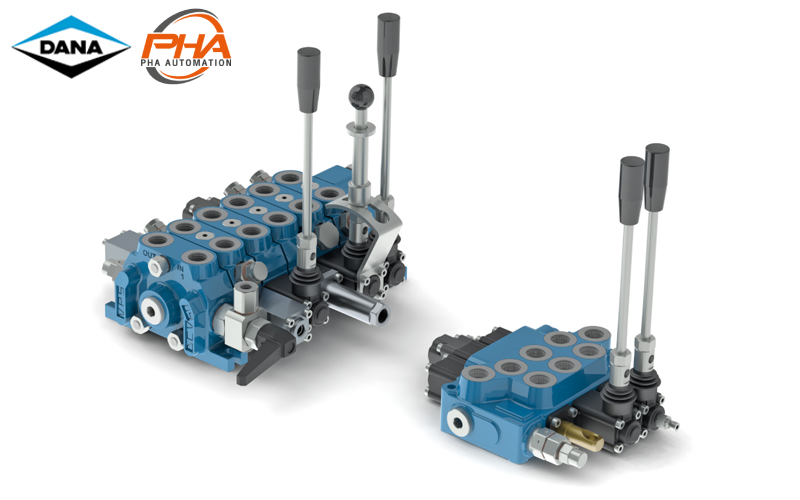
DANA Mobile valves - DCV series

DANA Mobile valves – DCV series
Feature | DANA Mobile valve DCV
Infact the project of each single valve and the choice of the better materials, machined with the highest tecnologies and under the strongest controls in each process, allow highest characteristics and numerous applications described in the following pages.
-
-
- all the casting are made in Shell-Moulding, in special graphite cast iron. This kind of cast iron is in higt resistance, and it allows to have, with the same external overall dimensions, bigger internal gallery, and lower pressure drops
- all spools are made in high resistance steel, nichel plated, radial balanced and with special notches in order to have a better sensibility
- all springs are made in high resistence steel. Pressure setting springs are pressed before testing
- max tolerance of spool housing is 2 micron
- internal leakage at 120 bar, 50° C and oil 30 cSt is beetwen 1 and 2 cm³/min, depending from the kind of spool and the kind of valve.
-
| General condition of work | DCV series |
|---|---|
| Max working temperature | -25 – 80 °C |
| Suggested working temperature | 30 – 60 °C |
| Max back pressure | 20 bar [290 PSI] |
| Max contrmination level | NAS 1638 class 9 (19/16 ISO-4406) |
| Fluid oil | Mineral oil |
| Kinematic viscosity | 10 – 460 mm2/s |
| Filtration | β 12 ≥ 75 |
Spool are available with different metering, marine protected, Viton® seals, special spring, etc.
Specifications | DANA Mobile Valve DCV
| Model | Monoblock Valves | Modular Valves | ||||||
|---|---|---|---|---|---|---|---|---|
| DCV 20 | DCV 40 | DCV 30 | DCV 50 | DCV 80 | DCV MG | |||
| Features | Max section | N.o | 6 | 6 | 12 | 12 | 12 | 10 |
| Max flow | l/min | 40 | 70 | 40 | 70 | 120 | 230 | |
| GPM | 10.6 | 18.5 | 10.6 | 18.5 | 31.7 | 60.7 | ||
| Max pressure | BAR | 400 | 400 | 350 | 350 | 350 | 350 | |
| psi | 5800 | 5800 | 5075 | 5075 | 5075 | 5075 | ||
| Circuit | Parallel | • | • | • | • | • | • | |
| Series | • | • | • | • | ||||
| Tandem | • | • | • | • | ||||
| Main relef V. | Direct | • | • | • | ||||
| Piloted | • | • | • | |||||
| Port relief valves | Overload | • | • | • | • | • | • | |
| Anti cavitation | • | • | • | • | • | |||
| Combined | • | • | • | • | • | |||
| Threads | BSP ISO 228/1 Cavity ISO 1179 |
A-B | 3/8″ | 1/2″ | 3/8″ | 1/2″ | 3/4″ | 1 |
| 3/8″ (1) | 1/2″ (1) | 3/4″ (1) | ||||||
| P | 3/8″ | 1/2″ | 3/8″ | 1/2″ | 3/4″ | 1 | ||
| 3/8″ (1) | 1/2″ (1) | 3/4″ (1) | ||||||
| T (Standard) |
3/8″ | 1/2″ | 3/8″ (3) | 1/2″ (3) | 3/4″ | 1 | ||
| 3/8″ (1) | 1/2″ (2) | 3/4″ (2) | 1/2″ (1) | 3/4″ (1) | ||||
| T (4) | – | – | 1/2″ | 3/4″ | 3/4″ | 1″ | ||
| SAE ISO 263 Cavity |
A-B | 9/16″-18UNF (SAE 6) |
3/4″-16UNF (SAE 8) |
9/16″-18UNF (SAE 6) |
7/8″-14UNF (SAE 10) |
1″ 1/16-12UN (SAE 12) |
1″ 5/16-12UN (SAE 16) |
|
| 7/8″-14UNF (SAE 10) (1) |
7/8″-14UNF (SAE 10) (1) |
|||||||
| P | 9/16″-18UNF (SAE 6) |
3/4″-16UNF (SAE 8) |
9/16″-18UNF (SAE 6) |
7/8″-14UNF (SAE 10) |
1″ 1/16-12UN (SAE 12) |
1″ 5/16-12UN (SAE 16) |
||
| 7/8″-14UNF (SAE 10) (1) |
7/8″-14UNF (SAE 10) (1) |
|||||||
| T (Standard) |
9/16″-18UNF (SAE 6) |
3/4″-16UNF (SAE 8) |
9/16″-18UNF (SAE 6) (3) |
7/8″-14UNF (SAE 10) (3) |
1″ 1/16-12UN (SAE 12) (3) |
1″ 5/16-12UN (SAE 16) |
||
| 7/8″-14UNF (SAE 10) (1) |
3/4″-16UNF (SAE 8) (2) |
1″ 1/16-12UN (SAE 12) (2) |
7/8″-14UNF (SAE 10) (1-3) |
|||||
| T (4) | – | – | 3/4″-16UNF (SAE 8) |
1″ 1/16-12UN (SAE 12) |
1″ 1/16-12UN (SAE 12) |
– | ||
| Spool stroke | A÷B | mm | ±5 | ±5 | ±5 | ±5 | ±7 | ±8 |
| inch | ±0.20 | ±0.20 | ±0.20 | ±0.20 | ±0.28 | ±0.31 | ||
| 4th position | mm | -3.5 | -5 | -3.5 | -5 | -5.5 | -5.5 | |
| inch | -0.14 | -0.20 | -0.14 | -0.20 | -0.22 | 0.22 | ||
| Series | mm | – | – | ±4.5 | ±4.5 | ±5.5 | ±8 | |
| inch | ±0.18 | ±0.18 | ±0.22 | ±0.31 | ||||
- (1) Threads availables on request
- (2) Threads availables on requestsolo only for outlet side
- (3) Inlet section with top output
- (4) Output section with stadard upper thread + carry over
ติดต่อแผนก HYDRAULIC


