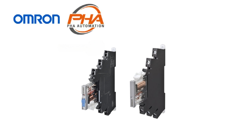
OMRON General Purpose Relay – G2RV-SR
Model Numbers | General Purpose Relay – G2RV-SR
Model Number Structure
Model Number Legend

Ordering Information
| Terminal (Wire connection) |
Classification | Latching lever (Test switch) |
Rated input voltage (V) |
Model | |
|---|---|---|---|---|---|
| Push-In Plus Terminal |
Standard | No | DC | 12 | G2RV-SR500 DC12 |
| 24 | G2RV-SR500 DC24 | ||||
| AC/DC | 24 | G2RV-SR500 AC/DC24 | |||
| 48 | G2RV-SR500 AC/DC48 | ||||
| AC | 100 | G2RV-SR500 AC100 | |||
| 110 | G2RV-SR500 AC110 | ||||
| 200 | G2RV-SR500 AC200 | ||||
| 230 | G2RV-SR500 AC230 | ||||
| Yes | DC | 24 | G2RV-SR501 DC24 | ||
| AC/DC | 24 | G2RV-SR501 AC/DC24 | |||
| Microloads | No | DC | 12 | G2RV-SR500-AP DC12 | |
| 24 | G2RV-SR500-AP DC24 | ||||
| AC/DC | 24 | G2RV-SR500-AP AC/DC24 | |||
| 48 | G2RV-SR500-AP AC/DC48 | ||||
| AC | 100 | G2RV-SR500-AP AC100 | |||
| 110 | G2RV-SR500-AP AC110 | ||||
| 200 | G2RV-SR500-AP AC200 | ||||
| 230 | G2RV-SR500-AP AC230 | ||||
| Screw terminal | Standard | No | DC | 12 | G2RV-SR700 DC12 |
| 24 | G2RV-SR700 DC24 | ||||
| AC/DC | 24 | G2RV-SR700 AC/DC24 | |||
| 48 | G2RV-SR700 AC/DC48 | ||||
| AC | 100 | G2RV-SR700 AC100 | |||
| 110 | G2RV-SR700 AC110 | ||||
| 200 | G2RV-SR700 AC200 | ||||
| 230 | G2RV-SR700 AC230 | ||||
| Yes | DC | 24 | G2RV-SR701 DC24 | ||
| AC/DC | 24 | G2RV-SR701 AC/DC24 | |||
| Microloads | No | DC | 12 | G2RV-SR700-AP DC12 | |
| 24 | G2RV-SR700-AP DC24 | ||||
| AC/DC | 24 | G2RV-SR700-AP AC/DC24 | |||
| 48 | G2RV-SR700-AP AC/DC48 | ||||
| AC | 100 | G2RV-SR700-AP AC100 | |||
| 110 | G2RV-SR700-AP AC110 | ||||
| 200 | G2RV-SR700-AP AC200 | ||||
| 230 | G2RV-SR700-AP AC230 | ||||
Note: Sockets are not sold individually.
Relay for Maintenance
Model Number Legend
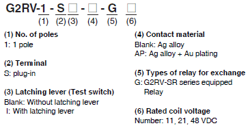
| Type | Latching Lever (Test switch) |
Rated coil voltage (V) |
Model | Applicable model | |
|---|---|---|---|---|---|
| Standard | No | DC | 11 | G2RV-1-S-G DC11 | G2RV-SR700/500 DC12V |
| 21 | G2RV-1-S-G DC21 | G2RV-SR700/500 DC24V | |||
| G2RV-SR700/500 AC/DC24V | |||||
| 48 | G2RV-1-S-G DC48 | G2RV-SR700/500 AC/DC48V | |||
| G2RV-SR700/500 AC100V | |||||
| G2RV-SR700/500 AC110V | |||||
| G2RV-SR700/500 AC200V | |||||
| G2RV-SR700/500 AC230V | |||||
| Yes | DC | 21 | G2RV-1-SI-G DC21 | G2RV-SR701/501 DC24V | |
| G2RV-SR701/501 AC/DC24V | |||||
| Microload | No | DC | 11 | G2RV-1-S-AP-G DC11 | G2RV-SR700/500-AP DC12V |
| 21 | G2RV-1-S-AP-G DC21 | G2RV-SR700/500-AP DC24V | |||
| G2RV-SR700/500-AP AC/DC24V | |||||
| 48 | G2RV-1-S-AP-G DC48 | G2RV-SR700/500-AP AC/DC48V | |||
| G2RV-SR700/500-AP AC100V | |||||
| G2RV-SR700/500-AP AC110V | |||||
| G2RV-SR700/500-AP AC200V | |||||
| G2RV-SR700/500-AP AC230V | |||||
Note: Voltage is reduced within the socket for the slim I/O relay, so the rated input voltage and rated coil voltage of
replacement relays are different.
Accessories (order separately)
Short Bars
| Appearance | Pitch | No. of poles |
Colors | Model * | Minimum order (Quantity) |
Maximum energizing current |
|---|---|---|---|---|---|---|
 |
6.2 mm | 2 | Red (R), Blue (S), Yellow (Y) |
PYDN-6.2-020[] | 10 | 32 A |
| 3 | PYDN-6.2-030[] | |||||
| 4 | PYDN-6.2-040[] | |||||
| 10 | PYDN-6.2-100[] | |||||
| 20 | PYDN-6.2-200[] |
Note: Use for wiring to the adjacent socket.
* Replace the box ([]) in the model number with the code for the covering color. [] color selection: R = red, S = blue, Y = yellow
Label
| Appearance | Model | Minimum order (Sheet) (Pieces per sheet) |
|---|---|---|
 |
XW5Z-P2.5LB1 * | 5 (1 sheet/72 pieces) |
| XW5Z-P2.5LB2 |
* Available following June 2017 production.
Separate Plate
| Appearance | Model |
|---|---|
 |
XW5Z-EP12 |
PLC interface unit
| Appearance | I/O classification | Connection method | Common process | Applicable Models * | Model |
|---|---|---|---|---|---|
 |
For input | Push-In | PNP | G2RV-SR500-AP | P2RVC-8-I-5-1 |
| NPN | P2RVC-8-I-5 | ||||
| Screw | PNP | G2RV-SR700-AP | P2RVC-8-I-7-1 | ||
| For output | Push-In | PNP | G2RV-SR500 G2RV-SR501 G3RV-SR500 |
P2RVC-8-O-5-1 | |
| NPN | P2RVC-8-O-5 | ||||
| Screw | PNP | G2RV-SR700 G2RV-SR701 G3RV-SR700 |
P2RVC-8-O-7-1 |
* Please make sure applicable models, P2RVC can not be used other combination than the above table.
Parts for DIN Track Mounting
| Appearance | Type | Model | Minimum order (Quantity) |
|
|---|---|---|---|---|
 |
DIN Tracks | 1 m | PFP-100N | 1 |
| 0.5 m | PFP-50N | |||
 |
End Plate * | PFP-M | 10 | |
 |
Spacer | PFP-S | ||
* When mounting DIN Track, please use End Plate (PFP-M).
Applicable Cables
| Name | Appearance | Cable length L (mm) |
Connecting Cables | Applicable Connectors | |
|---|---|---|---|---|---|
| Cables with Loose Wires P2RV-A[]C |
8 I/O points |
 |
1,000 | P2RV-A100C | Various devices |
| 2,000 | P2RV-A200C | ||||
| 3,000 | P2RV-A300C | ||||
| 5,000 | P2RV-A500C | ||||
| OMRON PLC Connecting Cables with Connectors (1:4) P2RV-4-[]C |
32 output points |
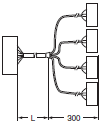 |
1,000 | P2RV-4-100C | PLC I/O Units with MIL connectors (1:4) CJ1W-OD232/OD262, etc. |
| 2,000 | P2RV-4-200C | ||||
| 3,000 | P2RV-4-300C | ||||
| 5,000 | P2RV-4-500C | ||||
| OMRON PLC Connecting Cables with Connectors (1:4) P2RV-4-[]IMC |
32 input points |
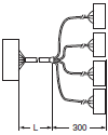 |
1,000 | P2RV-4-100IMC | PLC I/O Units with MIL connectors (1:4) CJ1W-ID232/ID262, etc. *1 |
| 2,000 | P2RV-4-200IMC | ||||
| 3,000 | P2RV-4-300IMC | ||||
| 5,000 | P2RV-4-500IMC | ||||
| OMRON PLC Connecting Cables with Connectors (1:4) P2RV-4-[]IFC |
32 input points |
 |
1,000 | P2RV-4-100IFC | PLC I/O Units with Fujitsu connectors (1:4) CJ1W-ID231/ID261, etc. *2 |
| 2,000 | P2RV-4-200IFC | ||||
| 3,000 | P2RV-4-300IFC | ||||
| 5,000 | P2RV-4-500IFC | ||||
| OMRON PLC Connecting Cables with Connectors (1:1) P2RV-A[]C-OMR GRT1 | 8 output points |
 |
500 | P2RV-A050C-OMR GRT1 | Slice I/O Units (1:1) For inputs: GRT1-ID8-1 For outputs: GRT1-OD8-1 |
| 1,000 | P2RV-A100C-OMR GRT1 | ||||
| 8 input points |
500 | P2RV-A050IC-OMR GRT1 | |||
| 1,000 | P2RV-A100IC-OMR GRT1 | ||||
| OMRON PLC Connecting Cables with Connectors (1:1) P2RV-A[]C-OMR NX |
8 output points |
 |
500 | P2RV-A050C-OMR NX | PLC I/O Units with screw-less clamp terminal block (1:1) For inputs: NX-ID4442 For outputs: NX-OD4256 |
| 1,000 | P2RV-A100C-OMR NX | ||||
| 8 input points |
500 | P2RV-A050IC-OMR NX | |||
| 1,000 | P2RV-A100IC-OMR NX | ||||
| Schneider Electric PLC Connecting Cables P2RV-[]C-SCH-[] |
32 input points |
 |
500 | P2RV-050C-SCH-A | Schneider Electric PLCs with 32-point connectors (1:4) For inputs: 140 DDI 353 00 For outputs: 140 DDO 353 00 |
| 1,000 | P2RV-100C-SCH-A | ||||
| 2,000 | P2RV-200C-SCH-A | ||||
| 3,000 | P2RV-300C-SCH-A | ||||
| 5,000 | P2RV-500C-SCH-A | ||||
| 32 output points |
500 | P2RV-050C-SCH-B | |||
| 1,000 | P2RV-100C-SCH-B | ||||
| 2,000 | P2RV-200C-SCH-B | ||||
| 3,000 | P2RV-300C-SCH-B | ||||
| 5,000 | P2RV-500C-SCH-B | ||||
| 16 input points |
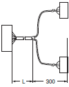 |
500 | P2RV-050C-SCH-C | Schneider Electric PLCs with 16-point connectors (1:2) For inputs: BMX DDI 1602 For outputs: BMX DDO 1602 |
|
| 1,000 | P2RV-100C-SCH-C | ||||
| 2,000 | P2RV-200C-SCH-C | ||||
| 3,000 | P2RV-300C-SCH-C | ||||
| 5,000 | P2RV-500C-SCH-C | ||||
| 16 output points |
500 | P2RV-050C-SCH-D | |||
| 1,000 | P2RV-100C-SCH-D | ||||
| 2,000 | P2RV-200C-SCH-D | ||||
| 3,000 | P2RV-300C-SCH-D | ||||
| 5,000 | P2RV-500C-SCH-D | ||||
| Siemens PLC Connecting Cables P2RV-[]C-SIM-[] |
32 input points |
 |
500 | P2RV-050C-SIM-A | Siemens PLCs with 32-point connectors (1:4) For inputs: 6ES7 321-1BL00-0AA0 For outputs: 6ES7 322-1BL00-0AA0 |
| 1,000 | P2RV-100C-SIM-A | ||||
| 2,000 | P2RV-200C-SIM-A | ||||
| 3,000 | P2RV-300C-SIM-A | ||||
| 5,000 | P2RV-500C-SIM-A | ||||
| 32 output points |
500 | P2RV-050C-SIM-B | |||
| 1,000 | P2RV-100C-SIM-B | ||||
| 2,000 | P2RV-200C-SIM-B | ||||
| 3,000 | P2RV-300C-SIM-B | ||||
| 5,000 | P2RV-500C-SIM-B | ||||
| 16 input points |
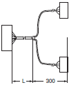 |
500 | P2RV-050C-SIM-C | Siemens PLCs with 16-point connectors (1:2) For inputs: 6ES7 321-1BH02-0AA0 |
|
| 1,000 | P2RV-100C-SIM-C | ||||
| 2,000 | P2RV-200C-SIM-C | ||||
| 3,000 | P2RV-300C-SIM-C | ||||
| 5,000 | P2RV-500C-SIM-C | ||||
| 32 input points |
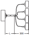 |
500 | P2RV-050C-SIM-D | Siemens PLCs with 32-point connectors (1:4) For inputs: 6ES7 421-1BL-0AA0 For outputs: 6ES7 422-1BL-0AA0 |
|
| 1,000 | P2RV-100C-SIM-D | ||||
| 2,000 | P2RV-200C-SIM-D | ||||
| 3,000 | P2RV-300C-SIM-D | ||||
| 5,000 | P2RV-500C-SIM-D | ||||
| 32 output points |
500 | P2RV-050C-SIM-E | |||
| 1,000 | P2RV-100C-SIM-E | ||||
| 2,000 | P2RV-200C-SIM-E | ||||
| 3,000 | P2RV-300C-SIM-E | ||||
| 5,000 | P2RV-500C-SIM-E | ||||
*1. Use the P2RVC-8-I-[]-1(PNP) as the PLC interface unit when connecting to the CJ1W-ID232/ID262 (or a unit with an equivalent terminal arrangement).
*2. Use the P2RVC-8-I-[]-1(PNP) as the PLC interface unit when connecting to the CJ1W-ID231/ID261 (or a unit with an
equivalent terminal arrangement).
Specifications | General Purpose Relay – G2RV-SR
Ratings
Coil ratings
| Rated input voltage |
Rated current | Must operate voltage |
Must release voltage |
Power consumption | Maximum allowable voltage |
|||
|---|---|---|---|---|---|---|---|---|
| AC | DC | Percentage of the rated voltage |
AC (VA) | DC (mW) | Percentage of the rated voltage |
|||
| 50 Hz | 60 Hz | |||||||
| 12 VDC | – | – | 27.9 mA | 80% max.* | 10% min. | – | Approx. 300 mW | 110% |
| 24 VDC | – | – | 13.5 mA | – | Approx. 300 mW | |||
| 24 VAC/VDC | 12.5 mA | 12.6 mA | 12.6 mA | Approx. 0.5 VA | Approx. 300 mW | |||
| 48 VAC/VDC | 5.9 mA | 6.1 mA | 5.2 mA | Approx. 0.4 VA | Approx. 250 mW | |||
| 100 VAC | 5.9 mA | 6.0 mA | – | Approx. 0.8 VA | – | |||
| 110 VAC | 5.9 mA | 5.9 mA | – | Approx. 0.8 VA | – | |||
| 200 VAC | 6.6 mA | 7.6 mA | – | Approx. 1.7 VA | – | |||
| 230 VAC | 7.3 mA | 8.4 mA | – | Approx. 1.7 VA | – | |||
Note: The operating characteristics are measured at ambient temperature of 23°C.
* Operating voltage will be, for mounting in the upside down direction, 85% max.
(Upside down: Direction in which the mechanical indicator faces down)
Contact ratings
| Item | Standard (G2RV-SR700, 500, 701, 501) |
For microloads (G2RV-SR700-AP, 500-AP) *2 |
|
|---|---|---|---|
| Contact configuration | SPDT | ||
| Load | Resistive load (cosφ=1) |
Inductive load (cosφ=0.4, L/R=7ms) |
Resistive load (cosφ=1) |
| Rated load | 6 A at 250 VAC 6 A at 30 VDC |
2.5 A at 250 VAC 2 A at 30 VDC |
50 mA at 30 VAC 50 mA at 36 VDC |
| Rated carry current | 6 A | 50 mA | |
| Maximum switching voltage | 440 VAC, 125 VDC | 30 VAC, 36 VDC | |
| Maximum switching current | 6 A | 50 mA | |
| Maximum switching power | 1,500 VA 180 W |
500 VA 60 W |
– |
| Failure rate P value (reference value) *1 |
10 mA at 5 VDC | 1 mA at 100 mVDC | |
*1. P level: λ60=0.1×10⁻⁶/times
This value is the value in switching frequency 120 operations/min.
*2. If the Au plating layer is destroyed, the number will be the same as the standard type.
Characteristics
| Item | Standard (G2RV-SR700, 500, 701, 501) |
For microloads (G2RV-SR700-AP, 500-AP) |
|
|---|---|---|---|
| Contact resistance *1 | 100 mΩ max. | ||
| Operate (Set) time *1 | 20 ms max. | ||
| Release time *1 | AC, AC/DC: 40 ms max. DC: 20 ms max. |
||
| Maximum operating frequency |
Mechanical: 18,000 operations/h Electrical: 1,800 operations/h (rated load) |
||
| Insulation resistance | 1,000 MΩ min. (at 500 VDC) | ||
| Dielectric strength | Between coil and contacts: 4,000VAC 50/60 Hz 1 min Contact between the same polarity: 1,000 VAC 50/60 Hz 1 min |
||
| Vibration resistance *2 | Destruction: 10 to 55 to 10 Hz, single amplitude 0.50 mm (double amplitude 1.0 mm) Malfunction: 10 to 55 to 10 Hz, single amplitude 0.50 mm (double amplitude 1.0 mm) |
||
| Shock resistance *2 | Destruction: 1,000 m/s2 Malfunction: Energized 200m/s2, Non-energized 100m/s2 |
||
| Endurance *1 | Mechanical | 5,000,000 operations min. | |
| Electrical | NO contact: 70,000 operations min. NC contact: 50,000 operations min. |
5,000,000 operations min. | |
| Ambient operating temperature |
Operating: -40 to +55°C (with no icing or condensation) | ||
| Ambient operating humidity |
Operating: 5 to 85% RH | ||
| Weight | Approx. 30 g | ||
| Contact material | Ag alloy | Ag alloy + Au plating | |
Note: Above values are initial values.
*1. Value is at ambient temperature of 23°C.
*2. Value when the end plate is used.
Approved standards
UL508 (file No.E41643)
| Model | Contact form | Operation coil ratings | Contact ratings | Operations |
|---|---|---|---|---|
| G2RV-SR series | SPDT | 12 to 48 VDC 24 to 230 VAC |
6 A at 250 VAC (Resistive load) 6 A at 30 VDC (Resistive load) 2 A at 400 VAC (Resistive load)* |
6,000 |
* If the load voltage exceeds 250 VAC, please attach with a spacing of 12 mm min., or use a separate plate (XW5Z-EP12).

TÜV (EN 61810-1)
| Model | Contact form | Operation coil ratings | Contact ratings | Operations |
|---|---|---|---|---|
| G2RV-SR series | SPDT | 12, 24 VDC 24, 48 VAC/VDC 100, 110, 200, 230 VAC |
6 A at 250 VAC (Resistive load) 6 A at 30 VDC (Resistive load) 2 A at 400 VAC (Resistive load)* |
50,000 50,000 6,000 |
* If the load voltage exceeds 250 VAC, please attach with a spacing of 12 mm min., or use a separate plate (XW5Z-EP12).

Lloyd’s (File No.07/10020)
| Model | Contact form | Operation coil ratings | Contact ratings |
|---|---|---|---|
| G2RV-SR500 G2RV-SR700 |
SPDT | 12, 24 VDC 24, 48 VAC/VDC 100, 110, 200, 230 VAC |
6 A at 250 VAC (Resistive load) |
| 2.5 A at 250 VAC (PF0.4) | |||
| 6 A at 30 VAC (Ress) | |||
| 2 A at 30 VDC (L/R=7ms) | |||
| G2RV-SR501 G2RV-SR701 |
SPDT | 12, 24 VDC 24 VAC/VDC |
6 A at 250 VAC (Resistive load) |
| 2.5 A at 250 VAC (PF0.4) | |||
| 6 A at 30 VAC (Ress) | |||
| 2 A at 30 VDC (L/R=7ms) | |||
| G2RV-SR500-AP G2RV-SR700-AP |
SPDT | 12, 24 VDC 24, 48 VAC/VDC 100, 110, 200, 230 VAC |
0.05 A at 30 VAC (Resistive load) 0.05 A at 36 VDC (Resistive load) |
Dimensions | General Purpose Relay – G2RV-SR
(Unit: mm)
Slim I/O Relay + socket
Push-In Plus Terminal Block
Models without latching lever (without test switch)
G2RV-SR500
G2RV-SR500-AP

Note: For recommended ferrules, crimp tools, and types and gauges of wires, refer to 3. Recommended Ferrules and Crimp Tools on Data Seet.
Models with latching lever (with test switch)
G2RV-SR501

Note: For recommended ferrules, crimp tools, and types and gauges of wires, refer to 3. Recommended Ferrules and Crimp Tools on Data Sheet.
Screw terminal
Models without latching lever (without test switch)
G2RV-SR700
G2RV-SR700-AP

Note: For recommended ferrules, crimp tools, and types and gauges of wires, refer to 3. Recommended Ferrules and Crimp Tools on Data Sheet.
Models with latching lever (with test switch)
G2RV-SR701

Note: For recommended ferrules, crimp tools, and types and gauges of wires, refer to 3. Recommended Ferrules and Crimp Tools on Data Sheet.
Relay for maintenance
Models without latching lever
G2RV-1-S-G
G2RV-1-S-AP-G

Models with latching lever (test switch)
G2RV-1-SI-G

Accessories (order separately)
PLC interface unit
Push-IN
P2RVC-8-I-5(-1)
P2RVC-8-O-5(-1)

Screw
P2RVC-8-I-7-1
P2RVC-8-O-7-1

Except for PLC interface unit
Short Bars
PYDN-6.2-[][] (6.2 mm)

Separate Plate
XW5Z-EP12

Features | General Purpose Relay – G2RV-SR
G2RV-SR is a slim type General Purpose Relays, 6.2mm wide, helps to minimize the panel size, has Push in Plus technology, used to save wiring compared to conventional screw terminals. (60% less wiring time compared to traditional screw terminals) Since G2RV is a transparent case, the status can be confirmed. Of the contact with the naked eye And it is easy to confirm the anomaly in the operating area in the operating area (Installed position)
Properties | General Purpose Relay – G2RV-SR
| General Purpose Relay | G2RV-SR | |
|---|---|---|
| Rated voltage | 24, 48, 100, 110, 200, 230 VAC | |
| 12, 24, 48 VDC | ||
| Power consumption | 0.4 – 1.7 VA | |
| 250 – 300 mW | ||
| Contact configuration | SPDT | |
| Load rating | standard | 6 A ที่ 250 VAC, 6 A ที่ 30 VDC (Resistance load) |
| 2.5 A ที่ 250 VAC, 2 A ที่ 30 VDC (Inductive load) | ||
| For microloads | 50 mA ที่ 30 VAC, 50mA ที่ 36 VDC (Resistance load) | |
| Size (W x H x D) mm | G2RV-SR500 G2RV-SR500-AP G2RV-SR501 |
6.2 x 90 x 78 |
| G2RV-SR501 R2RV-SR701 |
6.2 x 90 x 81 | |
| Weight (g) | 30 | |
ติดต่อแผนก Automation & Robots


