OMRON General Purpose Relay – LY
Model Numbers | General Purpose Relay – LY
Model Number Structure
| Structure | Relays with Plug-in Terminals  |
Relays with PCB Terminals  |
Case-surface mounting  |
|||
|---|---|---|---|---|---|---|
| Classification | Number of poles | With operation indicators |
||||
| Standard models Compliance with Electrical Appliances and Material Safety Act |
1 | *LY1 | **LY1N | *LY1-0 | *LY1F | |
| 2 | *LY2 | **LY2N | *LY2-0 | *LY2F | ||
| Bifur- cated |
**LY2Z | **LY2ZN | **LY2Z-0 | **LY2ZF | ||
| 3 | *LY3 | **LY3N | *LY3-0 | *LY3F | ||
| 4 | *LY4 | **LY4N | *LY4-0 | *LY4F | ||
| Models with diode for coil surge absorption (DC coil specification only) |
1 | **LY1-D | **LY1N-D2 | — | — | |
| 2 | **LY2-D | **LY2N-D2 | — | — | ||
| Bifur- cated |
**LY2Z-D | **LY2ZN-D2 | — | — | ||
| 3 | **LY3-D | **LY3N-D2 | — | — | ||
| 4 | **LY4-D | **LY4N-D2 | — | — | ||
| Models with CR circuits for coil surge absorption (AC coil specification only) |
1 | — | — | |||
| 2 | **LY2-CR | **LY2N-CR | ||||
| Bifur- cated |
**LY2Z-CR | **LY2ZN-CR | ||||
Note:
1. Cells with a diagonal line cannot be manufactured. Ask your OMRON representative for details on manufacturing products for cells containing “—” in the above table.
2. If #187 tab terminals are required, use the LY1F-T2 or LY2F-T2 (single-pole or double-pole models only).
3. Refer to Catalog for information on plug-in terminal and socket combinations.
4. Items with an asterisk (*) in the table are certified for UL, CSA, and SEV. This is indicated with a certification mark on the products.
5. Items with two asterisks (**) in the table are certified for UL and CSA. This is indicated with a certificationmark on the products.
6. All models in the table are certified for IEC (TÜV).
7. The models with plug-in terminals (single-pole, double-pole, and 4-pole) were combined with the PTF-E for the EC Declaration of Conformity. These products display the CE Marking.
Ordering Information
When your order, specify the rated voltage.
Models with Plug-in Terminals
| Number of poles | 1 pole | 2 poles | |||
|---|---|---|---|---|---|
| Classification | Model | Rated voltage (V) | Model | Rated voltage (V) | |
| Models with single contacts |
Standard models | LY1 | 12, 24, 100/110, 110/120, or 200/220 VAC |
LY2 | 12, 24, 100/110,110/120, 200/220, or 220/240 VAC |
| 12, 24, 48, or 100/110 VDC | 12, 24, 48, or 100/110 VDC | ||||
| Models with built-in operation indicators |
LY1N | 12, 24, 100/110, 110/120, or 200/220 VAC |
LY2N | 12, 24, 100/110, 110/120, 200/220, or 220/240 VAC |
|
| 12, 24, or 100/110 VDC | 12, 24, 48, or 100/110 VDC | ||||
| Models with built-in diodes |
LY1-D | 12, 24, 48, or 100/110 VDC | LY2-D | 12, 24, 48, or 100/110 VDC | |
| Models with built-in diodes and operation indicators |
LY1N-D2 | 12, 24, or 48 VDC | LY2N-D2 | 12, 24, 48, or 100/110 VDC | |
| Models with built-in CR circuits |
— | — | LY2-CR | 100/110, 110/120, 200/220, or 220/240 VAC |
|
| Models with built-in CR circuits and operation indicators |
— | — | LY2N-CR | 100/110, 110/120, 200/220, or 220/240 VAC |
|
| Bifurcated contacts | Standard models | — | — | LY2Z | 100/110 or200/220 VAC |
| — | — | 12, 24, 48, or 100/110 VDC | |||
| Models with built-in operation indicators |
— | — | LY2ZN | 100/110, 110/120, 200/220, or 220/240 VAC |
|
| — | — | 12 or 24 VDC | |||
| Models with built-in diodes |
— | — | LY2Z-D | 12, 24, or 48 VDC | |
| Models with built-in diodes and operation indicators |
— | — | LY2ZN-D2 | 12, 24, or 100/110 VDC | |
| Models with built-in CR circuits |
— | — | LY2Z-CR | 100/110 VAC | |
| Models with built-in CR circuits and operation indicators |
— | — | LY2ZN-CR | 100, 110, 110/120, or 200/220 VAC |
|
| Number of poles | 3 poles | 4 poles | |||
|---|---|---|---|---|---|
| Classification | Model | Rated voltage (V) | Model | Rated voltage (V) | |
| Models with single contacts | Standard models | LY3 | 12, 24, 100/110, or 200/220 VAC |
LY4 | 12, 24, 100/110, or 200/220 VAC |
| 12, 24, 48, or 100/110 VDC | 12, 24, 48, or 100/110 VDC | ||||
| Models with built-in operation indicators |
LY3N | 12, 24, 100/110, or 200/220 VAC | LY4N | 12, 24, 100/110, or 200/220 VAC | |
| 12, 24, 48, or 100/110 VDC | 12, 24, 48, or 100/110 VDC | ||||
| Models with built-in diodes | LY3-D | 12, 24, 48, or 100/110 VDC | LY4-D | 12, 24, 48, or 100/110 VDC | |
| Models with built-in diodes and operation indicators | LY3N-D2 | 12, 24, or 100/110 VDC | LY4N-D2 | 12, 24, 48, or 100/110 VDC | |
| Models with built-in CR circuits | — | — | — | — | |
| Models with built-in CR circuits and operation indicators | — | — | — | — | |
| Bifurcated contacts | Standard models | — | — | — | — |
| — | — | — | — | ||
| Models with built-in operation indicators |
— | — | — | — | |
| — | — | — | — | ||
| Models with built-in diodes | — | — | — | — | |
| Models with built-in diodes and operation indicators | — | — | — | — | |
| Models with built-in CR circuits | — | — | — | — | |
| Models with built-in CR circuits and operation indicators | — | — | — | — | |
Relays with PCB Terminals
| Number of poles |
1 pole | 2 poles | 3 poles | 4 poles | ||||
|---|---|---|---|---|---|---|---|---|
| Classification | Model | Rated voltage (V) | Model | Rated voltage (V) | Model | Rated voltage (V) | Model | Rated voltage (V) |
| Models with single contacts | LY1-0 | 24,100/110, 110/120, or 200/220 VAC |
LY2-0 | 12, 24, 100/ 110, 110/120, 200/220, or 220/240 VAC |
LY3-0 | 24, 100/110, or 200/220 VAC |
LY4-0 | 24, 100/110, or 200/ 220 VAC |
| 12 or 24 VDC | 12, 24, 48 or 100/110 VDC |
12, 24, 48, or 100/110 VDC |
12, 24, 48, or 100/110 VDC |
|||||
| Bifurcated contacts |
— | — | LY2Z-0 | 100/110 VAC | — | — | — | — |
| 24, 48, or 100/110 VDC |
||||||||
Case-surface Mounting
| Number of poles | 1 pole | 2 poles | 3 poles | 4 poles | ||||
|---|---|---|---|---|---|---|---|---|
| Classification | Model | Rated voltage (V) | Model | Rated voltage (V) | Model | Rated voltage (V) | Model | Rated voltage (V) |
| Models with single contacts |
LY1F | 24, 100/110, 110/120, 200/ 220, or 220/ 240 VAC |
LY2F | 12, 24, 100/ 110, 110/120, 200/220, or 220/240 VAC |
LY3F | 12, 24, 100/ 110, or 200/ 220 VAC |
LY4F | 12, 24, 100/ 110, or 200/ 220 VAC |
| 6, 12, 24, or 100/110 VDC |
12, 24, 48, or 100/110 VDC |
12, 24, or 100/110 VDC |
12, 24, or 100/110 VDC |
|||||
| Bifurcated contacts |
— | — | LY2ZF | 24, 100/110, or 200/220 VAC |
— | — | — | — |
| 12 or 24 VDC | ||||||||
Accessories (Order Separately)
Front-mounting Sockets
| Applicable relay model | Mounting Method | Conductive part protection | Terminal Type | Applicable crimp terminal / Electric wire | Appearance | Model | Hold-down Clips / Release Levers (Order Separately) |
|---|---|---|---|---|---|---|---|
| LY1[] LY2[] LY2[]-CR | Mounted on a DIN track or with screws |
Available | Push-In Plus Terminal |
Ferrules Solid wire Stranded wire |
 |
PTF-08-PU * LY2[]-CR cannot be used |
With release lever * Hold by release lever |
 |
PTF-08-PU-L | LY2[]-CR: Y92H-3 Other than those above: PYC-A1 |
|||||
| Screw terminal (M3.5 screw size) |
Forked terminals Solid wire Stranded wire |
 |
PTF08A-E * | ||||
| None | Round terminals Forked terminals Solid wire Stranded wire |
 |
PTF08A | ||||
| LY3[] | None | Screw terminal (M3.5 screw size) |
Round terminals Forked terminals Solid wire Stranded wire |
 |
PTF11A | PYC-A1 | |
| LY4[] | Available | Push-In Plus Terminal |
Ferrules Solid wire Stranded wire |
 |
PTF-14-PU-L | PYC-A1 | |
| Screw terminal (M3.5 screw size) |
Forked terminals Solid wire Stranded wire |
 |
PTF14A-E * | ||||
| None | Round terminals Forked terminals Solid wire Stranded wire |
 |
PTF14A |
* The PTF[]A-E Relays have finger protection. Round terminals cannot be used. Use forked terminals.
Back-mounting Sockets
| Applicable relay model |
Terminal Type | Appearance | Model | Hold-down Clips (Order Separately) |
|---|---|---|---|---|
| LY1[] LY2[] LY2[]-CR | Solder terminals |  |
PT08 * | LY2[]-CR: PYC-1 Other than those above: PYC-P |
| Wrapping terminals |  |
PT08QN | ||
| PCB terminals |  |
PT08-0 | ||
| LY3[] | Solder terminals |  |
PT11 * | PYC-P |
| Wrapping terminals |  |
PT11QN | ||
| PCB terminals |  |
PT11-0 | ||
| LY4[] | Solder terminals |  |
PT14 * | PYC-P |
| Wrapping terminals |  |
PT14QN | ||
| PCB terminals |  |
PT14-0 |
* When ordering PT08, PT11, or PT14 sockets, please note that the minimum order quantity is 10 and orders are accepted in multiples of the minimum order.
Relay Hold-down Clips
| Application | Used with Socket | Used with Socket mounting plate | For models with built-in CR circuits | ||
|---|---|---|---|---|---|
| Appearance |  |
 |
 |
 |
 |
| Model | PYC-A1 | PYC-P | PYC-S | Y92H-3 | PYC-1 |
| Minimum order (quantity) * |
100 | 100 | 10 | 10 | 10 |
* Orders are accepted in multiples of the minimum order.
Socket Mounting Plates
| Applicable sockets | Number of sockets | Model |
|---|---|---|
| PT08 PT08QN |
1 | PYP-1 *1 |
| 18 | PYP-18 *2 | |
| 36 | PYP-36 *2 | |
| PT11 PT11QN |
1 | PTP-1-3 |
| 12 | PTP-12 | |
| PT14 PT14QN |
1 | PTP-1 |
| 10 | PTP-10 |
*1. When ordering PYP-1, please note that the minimum order quantity is 10 and orders are accepted in multiples of the minimum order.
*2. PYP-18 and PYP-36 can be cut to any required length.
Specifications | General Purpose Relay – LY
Ratings
Standard Models with Built-in Operation Indicators
Operating Coil, Single-pole and Double-pole Models
| Item | Rated current (mA) | Coil resistance (Ω) | Coil inductance (H) | Must-operate voltage (V) | Must-release voltage (V) | Maximum voltage (V) | Power con- sumption (VA, W) | |||
|---|---|---|---|---|---|---|---|---|---|---|
| Rated voltage (V) | 50 Hz | 60Hz | Armature OFF | Armature ON | ||||||
| AC | 12 | 106.5 | 91 | 46 | 0.17 | 0.33 | 80% max. *1 | 30% min. *2 | 110% of rated voltage | Approx. 1.0 to 1.2 (at 60 Hz) |
| 24 | 53.8 | 46 | 180 | 0.69 | 1.3 | |||||
| 50 | 25.7 | 22 | 788 | 3.22 | 5.66 | |||||
| 100/110 | 11.7/12.9 | 10/11 | 3,750 | 14.54 | 24.6 | Approx. 0.9 to 1.1 (at 60 Hz) | ||||
| 110/120 | 9.9/10.8 | 8.4/9.2 | 4,430 | 19.2 | 32.1 | |||||
| 200/220 | 6.2/6.8 | 5.3/5.8 | 12,950 | 54.75 | 94.07 | |||||
| 220/240 | 4.8/5.3 | 4.2/4.6 | 18,790 | 83.5 | 136.4 | |||||
| DC | 6 | 150 | 40 | 0.16 | 0.33 | 10% min. *2 | Approx. 0.9 | |||
| 12 | 75 | 160 | 0.73 | 1.37 | ||||||
| 24 | 36.9 | 650 | 3.2 | 5.72 | ||||||
| 48 | 18.5 | 2,600 | 10.6 | 21.0 | ||||||
| 100/110 | 9.1/10 | 11,000 | 45.6 | 86.2 | ||||||
3 poles
| Item | Rated current (mA) | Coil resistance (Ω) | Coil inductance (H) | Must-operate voltage (V) | Must- release voltage (V) | Maximum voltage (V) | Power con- sumption (VA, W) | |||
|---|---|---|---|---|---|---|---|---|---|---|
| Rated voltage (V) | 50 Hz | 60Hz | Armature OFF | Armature ON | ||||||
| AC | 12 | 159 | 134 | 24 | 0.12 | 0.21 | 80% max. *1 | 30% min. *2 | 110% of rated voltage | Approx. 1.6 to 2.0 (at 60 Hz) |
| 24 | 80 | 67 | 100 | 0.44 | 0.79 | |||||
| 100/110 | 14.1/16 | 12.4/13.7 | 2,300 | 10.5 | 18.5 | |||||
| 200/220 | 9.0/10.0 | 7.7/8.5 | 8,650 | 34.8 | 59.5 | |||||
| DC | 12 | 112 | 107 | 0.45 | 0.98 | 10% min. *2 | Approx. 1.4 | |||
| 24 | 58.6 | 410 | 1.89 | 3.87 | ||||||
| 48 | 28.2 | 1,700 | 8.53 | 13.9 | ||||||
| 100/110 | 12.7/13 | 8,500 | 29.6 | 54.3 | ||||||
4 poles
| Item | Rated current (mA) | Coil resistance (Ω) | Coil inductance (H) | Must-operate voltage (V) | Must-release voltage (V) | Maximum voltage (V) | Power consumption (VA, W) | |||
|---|---|---|---|---|---|---|---|---|---|---|
| Rated voltage (V) | 50 Hz | 60Hz | Armature OFF | Armature ON | ||||||
| AC | 12 | 199 | 170 | 20 | 0.1 | 0.17 | 80% max. *1 | 30% min. *2 | 110% of rated voltage | Approx. 1.95 to 2.5 (at 60 Hz) |
| 24 | 93.6 | 80 | 78 | 0.38 | 0.67 | |||||
| 100/110 | 22.5/25.5 | 19/21.8 | 1,800 | 10.5 | 17.3 | |||||
| 200/220 | 11.5/13.1 | 9.8/11.2 | 6,700 | 33.1 | 57.9 | |||||
| DC | 12 | 120 | 100 | 0.39 | 0.84 | 10% min. *2 | Approx. 1.5 | |||
| 24 | 69 | 350 | 1.41 | 2.91 | ||||||
| 48 | 30 | 1,600 | 6.39 | 13.6 | ||||||
| 100/110 | 15/15.9 | 6,900 | 32.0 | 63.7 | ||||||
Note:
1. The rated current and coil resistance are measured at a coil temperature of 23°C with tolerances of +15%/ -20% for the AC rated current and ±15% for the DC coil resistance.
2. The AC coil resistance and inductance values are reference values only. (at 60 Hz).
3. Operating characteristics were measured at a coil temperature of 23°C. 4. The maximum voltage capacity was measured at an ambient temperature of 23°C.
*1. There is variation between products, but actual values are 80% max. To ensure operation, apply at least 80% of the rated value (at a coil temperature of +23° C).
*2. The actual values are 30% min. for AC and 10% min. for DC. To ensure release, use a value that is lower than the specified value.
Refer to List of Certified Models for a list of models that are certified for safety standards and the Electrical Appliances and Material Safety Act.
| Classification | 1 pole | Double-, 3-, and 4-pole models | Bifurcated contacts | |||
|---|---|---|---|---|---|---|
| Load | Resistive load | Inductive load (cos φ = 0.4, L/R = 7 ms) | Resistive load | Inductive load (cos φ = 0.4, L/R = 7 ms) | Resistive load | Inductive load (cos φ = 0.4, L/R = 7 ms) |
| Contact type | Single | Bifurcated | ||||
| Contact materials | Ag alloy | Ag | ||||
| Rated load | 15 A at 110 VAC 15 A at 24 VDC | 10 A at 110 VAC 7 A at 24 VDC | 10 A at 110 VAC 10 A at 24 VDC | 7.5 A at 110 VAC 5 A at 24 VDC | 5 A at 110 VAC 5 A at 24 VDC | 4 A at 110 VAC 4 A at 24 VDC |
| Rated carry current | 15 A | 10 A | 7 A | |||
| Maximum contact voltage | 250 VAC 125 VDC | 250 VAC 125 VDC | 250 VAC 125 VDC | |||
| Maximum contact current | 15 A | 15 A | 10 A | 10 A | 7 A | 7 A |
| Type | Single-pole and double-pole models (standard models and bifurcated contact models) | Single-pole, double-pole models (models with built-in operation indicators, models with built-in diodes, and models with built-in CR circuits), 3-pole and 4-pole models |
|---|---|---|
| Ambient operating temperature | -25 to 55°C (with no icing or condensation) *1 | -25 to +40°C (with no icing or condensation) *2 |
| Ambient operating humidity | 5% to 85% | |
Note:
1. Some models in the LY1 and LY2 Series have an upper temperature limit of +40°C. This limitation is due to the diode junction temperature and the elements used.
2. Refer to Ambient Temperature vs. Coil Temperature Rise in Engineering Data on Catalog for information on operation in temperature conditions that are not described here.
3. When you apply a minimum of 10 A of current to an LY1 when it is used in combination with the PTF-08-PU, PTF-08-PU-L, PTF08A, PTF08A-E, or PT08, connect each of the following terminal pairs: (1) to (2), (3) to (4), and (5) to (6).
*1. If the carry current is 4 A or less, the usable ambient temperature range is −25 to 70° C. *2. If the flowing current is 4 A or less, the usable ambient temperature range is -25 to 55° C.
Characteristics
| Type | Standard models, models with built-in operation indicators, models with built-in CR circuits, and models with built-in diodes | Bifurcated contacts | |
|---|---|---|---|
| Contact resistance *1 | 50 mΩ max. | ||
| Operating time *2 | 25 ms max. | ||
| Release time *2 | 25 ms max. | ||
| Maximum operating frequency | Mechanical | 18,000 operations/h | |
| Rated load | 1,800 operations/h | ||
| Insulation resistance *3 | 100 MΩ min. | ||
| Dielectric strength | Between coil and contacts | 2,000 VAC at 50/60 Hz for 1 min. | |
| Between contacts of different polarity | |||
| Between contacts of the same polarity | 1,000 VAC at 50/60 Hz for 1 min. | ||
| Vibration resistance | Destruction | 10 to 55 to 10 Hz, 0.5-mm single amplitude (1.0-mm double amplitude) | |
| Malfunction | 10 to 55 to 10 Hz, 0.5-mm single amplitude (1.0-mm double amplitude) | ||
| Shock resistance | Destruction | 1,000 m/s2 | |
| Malfunction | 200 m/s2 | ||
| Endurance | Mechanical | AC: 50,000,000 operations min. DC: 100,000,000 operations min. (switching frequency: 18,000 operations/h) | |
| Electrical *4 | 1-, 3-, 4-pole: 200,000 operations min. 2-pole: 500,000 operations min. (rated load, operating frequency: 1,800 operations/h) | 2-pole: 500,000 operations min. (rated load, operating frequency: 1,800 operations/h) | |
| Failure rate P value (reference value) *5 | 100 mA at 5 VDC | 10mA at 5 VDC | |
| Weight | 1-pole and 2-pole: 40 g, 3-pole: Approx. 50 g, 4-pole: Approx. 70 g | ||
Note: The values at the left are initial values.
*1. Measurement conditions: 1 A at 5 VDC using the voltage drop method
*2. Measurement conditions: With rated operating power applied, not including contact bounce. Ambient temperature condition: 23° C
*3. Measurement conditions: For 500 VDC applied to the same location as for dielectric strength measurement.
*4. Ambient temperature condition: 23° C *5. This value was measured at a switching frequency of 120 operations per minute.
Endurance Under Real Loads (Reference Only)
| Item | LY1, 100 VAC | LY2, 100 VAC | ||||
|---|---|---|---|---|---|---|
| Load type | Conditions | Operating frequency | Electrical life (×10,000 operations min.) | Conditions | Operating frequency | Electrical life (×10,000 operations min.) |
| AC motor | 400 W, 100 VAC single-phase with 35-A inrush current, 7-A current flow | ON for 10 s, OFF for 50 s | 5 | 200 W, 100 VAC single-phase with 25-A inrush current, 5-A current flow | ON for 10 s, OFF for 50 s | 20 |
| AC lamp | 300 W, 100 VAC with 51-A inrush current, 3-A current flow | ON for 5 s, OFF for 55 s | 10 | 300 W, 100 VAC with 51-A inrush current, 3-A current flow | ON for 5 s, OFF for 55 s | 8 |
| 500 W, 100 VAC with 78-A inrush current, 5-A current flow | 2.5 | |||||
| Capacitor (2,000 μF) | 24 VDC with 50-A inrush current, 1-A current flow | ON for 1 s, OFF for 6 s | 10 | 24 VDC with 50-A inrush current, 1-A current flow | ON for 1 s, OFF for 15 s | 1 |
| 24 VDC with 20-A inrush current, 1-A current flow | 15 | |||||
| AC solenoid | 50 VA with 2.5-A inrush current, 0.25-A current flow | ON for 1 s, OFF for 2 s | 150 | 50 VA with 2.5-A inrush current, 0.25-A current flow | ON for 1 s, OFF for 2 s | 100 |
| 100 VA with 5-A inrush current, 0.5-A current flow | 80 | 100 VA with 5-A inrush current, 0.5-A current flow | 50 | |||
| Item | LY4, 100 VAC | ||
|---|---|---|---|
| Load type | Conditions | Operating frequency | Electrical life (×10,000 operations min.) |
| AC motor | 200 W, 200 VAC three-phase with 5-A inrush current, 1-A current flow | ON for 10 s, OFF for 50 s | 50 |
| 750 W, 200 VAC three-phase with 18-A inrush current, 3.5-A current flow | 7 | ||
| AC lamp | 300 W, 100 VAC with 51-A inrush current, 3-A current flow | ON for 5 s, OFF for 55 s | 5 |
| Capacitor (2,000 μF) | 24 VDC with 50-A inrush current, 1-A current flow | ON for 1 s, OFF for 15 s | 0.5 |
| 24 VDC with 20-A inrush current, 1-A current flow | ON for 1 s, OFF for 2 s | 20 | |
| AC solenoid | 50 VA with 2.5-A inrush current, 0.25-A current flow | ON for 1 s, OFF for 2 s | 100 |
| 100 VA with 5-A inrush current, 0.5-A current flow | 50 | ||
Dimensions | General Purpose Relay – LY
(Unit: mm)
Solder terminals
LY1
LY1N
LY1-D
LY1N-D2

LY2, LY2-D
LY2Z, LY2Z-D
LY2N, LY2N-D2
LY2ZN, LY2ZN-D2

LY3
LY3N
LY3-D
LY3N-D2

LY4
LY4N
LY4-D
LY4N-D2

LY2-CR
LY2Z-CR
LY2N-CR
LY2ZN-CR

* These dimensions are for the LY2N-CR.
Relays with PCB Terminals
LY1-0, LY3-0, LY2-0, and LY4-0

Note: The dimensions depicted here are for the LY2-0.
The dimension with an asterisk (*) is 6.4 for the LY1-0.
Case-surface mounting
LY1F
LY2F

Note:
1. The figures and dimensions depicted here are for the LY1F. The LY2F is also conforms to these measurements. The dimension with an asterisk (*) for the LY2F is “eight, 3-dia. holes.”
2. For the LY1F-T2 and LY2F-T2 terminal (#187) dimensions, the hole dimension marked with an asterisk (*) is eight 1.55-dia. and the length marked with two asterisks (**) is 8.45.
LY3F

LY4F

Connection Sockets
PTF-08-PU(-L)

Mounting Hole Dimensions

PTF08A

PTF08A-E (Finger Protection Structure)

Mounting Hole Dimensions

PTF11A

Mounting Hole Dimensions

PTF-14-PU-L

Mounting Hole Dimensions

PTF14A

PTF14A-E (Finger Protection Structure)

Mounting Hole Dimensions

Note: If you use the PTF-08-PU, PTF-08-PU-L, PTF08A, PTF08A-E, or PT08 with an LY1 Relay, connect the following
terminal pairs: 1-2, 3-4, and 5-6 (for usage at 10 A or higher).
PT08

PT08QN

Mounting hole and PCB dimensions

PT08-0

Mounting hole and PCB dimensions

PT11

PT11QN
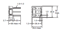
Mounting hole and PCB dimensions
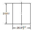
PT11-0
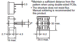
Mounting hole and PCB dimensions
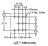
PT14
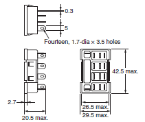
PT14QN
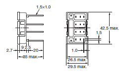
Mounting hole and PCB dimensions
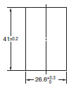
PT14-0
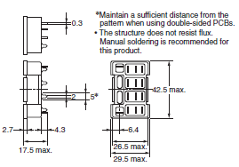
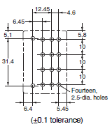
Mounting hole and PCB dimensions
Note: Use a panel with a thickness of 1 to 2 mm when mounting a Socket on it.
Hold-down Clips
PYC-A1
Approx. 0.54 g (per clip)
One Set (2 Clips)
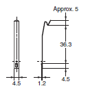
PYC-P
Approx. 1.4 g
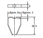
PYC-S
Approx. 1.8 g
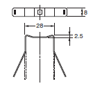
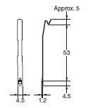
Y92H-3
Approx. 0.7 g (per clip)
One Set (2 Clips)
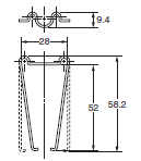
PYC-1
Approx. 6 g
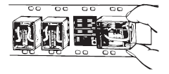
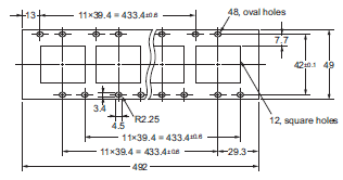
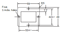
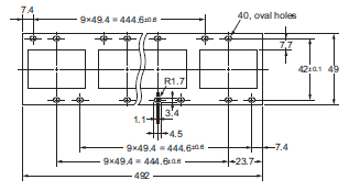
Socket Mounting Plates (t = 1.6)
OMRON can provide Socket Mounting Plate for convenient Socket installation. Please use these Plates as required.
PYP-1
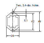
PYP-18
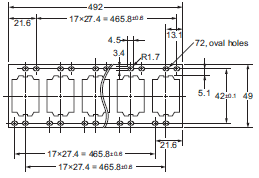
PYP-36
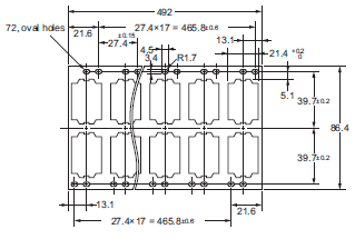
PTP-1-3
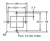
PTP-12
PTP-1
PTP-10
Features | General Purpose Relay – LY
- Wiring work can be shortened by as much as 60%* compared to conventional screw terminal sockets by combining with push-in plus terminal sockets (PYF-[]-PU) that feature light insertion force and strong pull-out strength to achieve less wiring work.
- The standard models include models that are compliant with the UL, CSA, and SEV safety standards and with the Electrical Appliances and Material Safety Act.
- Equipped with an arc barrier for arc interruption.
- Withstand voltages up to 2,000 V.
- New built-in diode and built-in CR circuit models have joined the series.
- The lineup also includes models that are compliant with the LR and VDE safety standards.
- Single-pole and double-pole models have AC4 ratings and DC2 ratings (operating coil ratings: 100/110 VAC, 110/120 VAC, 200/220 VAC, 220/240 VAC, and 100/110 VDC).
- Three-pole and four-pole models have AC4 ratings and DC2 ratings (operating coil ratings: 100/110 VAC, 200/220 VAC and 100/110 VDC).
- When both push-in plus terminals and screw terminal sockets are combined with plug-in terminal types (according to actual OMRON measurements as of November 2015)
Properties | General Purpose Relay – LY
| General Purpose Relay | LY | |
|---|---|---|
| Rated voltage | Single-pole and Double-pole | 12, 24, 50, 100/110, 110/120, 200/220, 220/240 VAC |
| 6, 12, 24, 48, 100/110 VDC | ||
| Three-pole | 12, 24, 100/110, 200/220 VAC | |
| 12, 48, 48, 100/110 VDC | ||
| Four-pole | 12, 24, 100/110, 200/220 VAC | |
| 12, 24, 48, 100/110 VDC | ||
| Power consumption | Single-pole and Double-pole | 0.9 – 1.2 VA |
| 0.9 W | ||
| Three-pole | 1.6 – 2.0 VA | |
| 1.4 W | ||
| Four-pole | 1.95 – 2.5 VA | |
| 1.5 W | ||
| Contact configuration | DPDT | |
| 3PDT | ||
| 4PDT | ||
| Rated load | 1 pole | 15 A ที่ 110 VAC, 15 A ที่ 24 VDC (resistive load) |
| 10 A ที่ 110 VAC, 7 A ที่ 24 VDC (Inductive load) | ||
| 2, 3, 4 pole | 10 A ที่ 110 VAC, 10 A ที่ 24 VDC (resistive load) | |
| 7.5 A ที่ 110 VAC, 5 A ที่ 24 VDC (Inductive load) | ||
| Bifurcated contact | 5 A ที่ 110 VAC, 5 A ที่ 24 VDC (resistive load) | |
| 5 A ที่ 110 VAC, 4 A ที่ 24 VDC (Inductive load) | ||
| Size (W x H x D) mm | Every Model | 21.5 x 36 x 28 |
| Only Model: MY2F, MY3F, MY4F, MY4ZF | 22.5 x 36 x 44 | |
| Weight (g) | 1, 2 pole | 40 |
| 3-pole | 50 | |
| 4-pole | 70 | |
ติดต่อแผนก Automation & Robots


