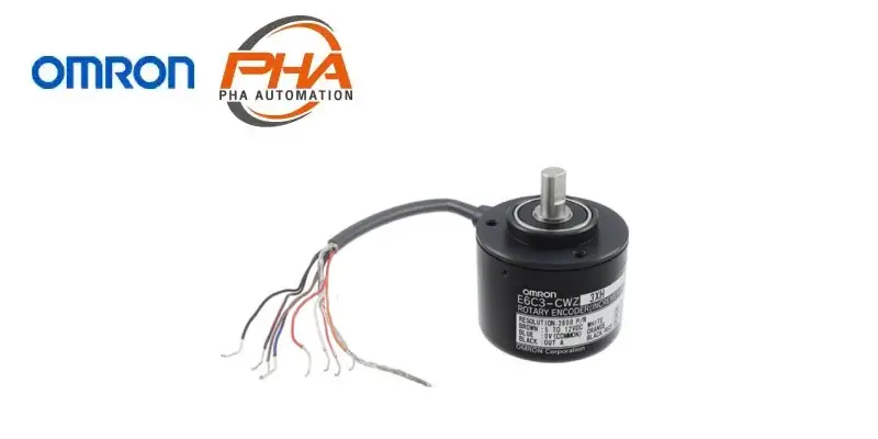
OMRON Rotary Encoder - E6C3-C

OMRON Rotary Encoder – E6C3-C
Model Numbers | Rotary Encoder – E6C3-C
Encoders
| Power supply voltage | Output configuration | Resolution (pulses/rotation) |
Connection method | Model |
|---|---|---|---|---|
| 12 to 24 VDC | Complementary output | 100, 200 | Pre-wired (1 m) * |
E6C3-CWZ5GH (resolution) 1M Example: E6C3-CWZ5GH 100P/R 1M |
| 300, 360, 500 | ||||
| 600, 720, 800 | ||||
| 1,000, 1,024, 1,200 | ||||
| 1,500, 1,800, 2,000 | ||||
| 2,048, 2,500, 3,600 | ||||
| 5 to 12 VDC | Voltage output | 100, 200 | E6C3-CWZ3EH (resolution) 1M Example: E6C3-CWZ3EH 100P/R 1M |
|
| 300, 360, 500 | ||||
| 600, 720, 800 | ||||
| 1,000, 1,024, 1,200 | ||||
| 1,500, 1,800, 2,000 | ||||
| 2,048, 2,500, 3,600 | ||||
| 5 to 12 VDC | Line-driver output | 100, 200 | E6C3-CWZ3XH (resolution) 1M Example: E6C3-CWZ3XH 100P/R 1M |
|
| 300, 360, 500 | ||||
| 600, 720, 800 | ||||
| 1,000, 1,024, 1,200 | ||||
| 1,500, 1,800, 2,000 | ||||
| 2,048, 2,500, 3,600 |
* Models with 2-m cable are also available. When ordering, specify the cable length at the end of the model number
(example: E6C3-CWZ5GH 300P/R 2M).
Accessories (Order Separately)
| Name | Model | Remarks |
|---|---|---|
| Couplings | E69-C08B | — |
| E69-C68B | Different end diameter (6 to 8 mm) | |
| Flanges | E69-FCA03 | — |
| E69-FCA04 | E69-2 Servo Mounting Bracket provided. | |
| Servo Mounting Bracket | E69-2 | Provided with E69-FCA04 Flange. |
Refer to Accessories for details.
Specifications | Rotary Encoder – E6C3-C
| Model | E6C3-CWZ5GH | E6C3-CWZ3EH | E6C3-CWZ3XH | |
|---|---|---|---|---|
| Power supply voltage | 12 VDC -10% to 24 VDC +15%, ripple (p-p): 5% max. |
5 VDC -5% to 12 VDC +10%, ripple (p-p): 5% max. |
||
| Current consumption *1 |
100 mA max. | |||
| Resolution (pulses/rotation) |
100, 200, 300, 360, 500, 600, 720, 800, 1,000, 1,024, 1,200, 1,500, 1,800, 2,000, 2,048, 2,500, 3,600 |
|||
| Output phases | Phases A, B, and Z *5 |  |
||
| Output configuration | Complementary outputs *2 | Voltage output (NPN output) | Line driver output *3 | |
| Output capacity | Output voltage: VH = Vcc = 3 V min. (IO = 30 mA) VL = 2 V max. (IO = -30 mA) Output current: ±30 mA |
Output resistance: 2 kΩ Output current: 35 mA max. Residual voltage: 0.7 V max. |
AM26LS31 equivalent Output current: High level: IO = -10 mA Low level: IS = 10 mA Output voltage: VO = 2.5 V min. VS = 0.5 V max. |
|
| Maximum response frequency *4 | 125 kHz (65 kHz when using phase Z reset) | |||
| Phase difference between outputs |
90°±45° between A and B (1/4 T ± 1/8 T) | |||
| Rise and fall times of output | 1 μs max. (Cable length: 2 m, Output current: 30 mA) |
1 μs max. (Cable length: 2 m, Output current: 35 mA) |
1 μs max. (Cable length: 2 m, IO: -10 mA, IS: 10 mA) |
|
| Starting torque | 10 mNm max. at room temperature, 30 mNm max. at low temperature | |||
| Moment of inertia | 2.0 × 10⁻⁶ kgm2 max.; 1.9 × 10⁻⁶ kgm2 max. at 500 P/R max. | |||
| Shaft loading |
Radial | 80 N | ||
| Thrust | 50 N | |||
| Maximum permissible speed |
5,000 r/min | |||
| Protection circuits | Output load short-circuit protection | — | ||
| Ambient temperature range |
Operating: -10 to 70°C (with no icing), Storage: -25 to 85°C (with no icing) | |||
| Ambient humidity range |
Operating/Storage: 35% to 85% (with no condensation) | |||
| Insulation resistance | 20 MΩ min. (at 500 VDC) between current-carrying parts and case | |||
| Dielectric strength | 500 VAC, 50/60 Hz for 1 min between current-carrying parts and case | |||
| Vibration resistance | Destruction: 10 to 500 Hz, 150 m/s2 or 2-mm double amplitude for 11 min 3 times each in X, Y, and Z directions |
|||
| Shock resistance | Destruction: 1,000 m/s2 3 times each in X, Y, and Z directions | |||
| Degree of protection | IEC 60529 IP65, in-house standards: oilproof | |||
| Connection method | Pre-wired Models (Standard cable length: 1 m) | |||
| Material | Case: Aluminum, Main unit: Aluminum, Shaft: SUS303 | |||
| Weight (packed state) | Approx. 300 g | |||
| Accessories | Instruction manual Note: Coupling, mounting bracket and hex-head spanner are sold separately. |
|||
*1. An inrush current of approximately 9 A will flow for approximately 0.1 ms when the power is turned ON.
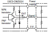
*2. Complementary Output
The complementary output has two output transistors (NPN and PNP) as shown below. These two output transistors
alternately turn ON and OFF depending on the high or low output signal. When using them, pull up to the positive
power supply voltage level or pull down to 0 V. The complementary output allows flow-in or flow-out of the output
current and thus the rising and falling speeds of signals are fast. This allows a long cable distance. They can be
connected to open-collector input devices (NPN, PNP).

*3. The line driver output is a data transmission circuit compatible with RS-422A and long-distance transmission is
possible with a twisted-pair cable. (AM26LS31 equivalent)
*4. The maximum electrical response speed is determined by the resolution and maximum response frequency as
follows:

This means that the Rotary Encoder will not operate electrically if its speed exceeds the maximum electrical
response speed.
*5. The phase Z signal is output when cut face D on the shaft and the cable connection direction are as shown in the
following diagram (output position range: ±15°).
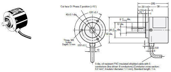
Dimensions | Rotary Encoder – E6C3-C
Tolerance class IT16 applies to dimensions in this datasheet unless otherwise specified.
Encoder
E6C3-CWZ[][]H

The E69-C08B Coupling is sold separately.
คุณสมบัติ | Rotary Encoder – E6C3-C
- เซนเซอร์วัดค่าทางการหมุนเพิ่มการกันน้ำสำหรับสภาพแวดล้อมที่เลวร้าย
- ป้องกันหยดน้ำและน้ำมัน
- เส้นผ่านศูนย์กลาง 50 มม.
- เพลาหมุนเส้นผ่านศูนย์กลาง 8 มม.
- ป้องกันไฟกระชาก
คุณสมบัติ | Rotary Encoder – E6C3-C
| สายไฟออกด้านข้าง |
| สายเชื่อมต่อแบบเปลือย |
| เอาต์พุตแบบเพิ่มขึ้น (Incremental) |
| ป้องกันสภาพแวดล้อมมาตรฐาน IP65 |
| รองรับความเร็วสูงสุด 5000 รอบต่อนาที |
| ความละเอียดสูงสุด 3600 ppr. |
ติดต่อแผนก Automation & Robots


